infra CONVERT
blue DAT • infra DAT
mdm TOOL
infra CONVERT
blue DAT • infra DAT
mdm TOOL
This is an old revision of the document!
User Manual infra CONVERT > More
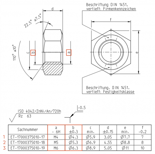
Below, we recommend a procedure for creating test plans for each individual component variant on the basis of a →collective drawing. The instructions refer to the following example “Hexagon nut in three variants”. The creation of characteristics is represented by the drawing entries with the reference symbols “a” and “b”.
| Step | Action | Result | |
|---|---|---|---|
| 1 | Create project | Create a new project and name it according to your documentation requirements. In this project, you create the inspection plans for all component variants in the next steps. | The project is created and named. |
| 2 | Creating a generic test plan | 1) Load the drawing sheets and name the first test plan version “Generic”. The generic inspection plan version will contain all characteristics that may occur (in different versions) in the component variants. In the “Version” input field, put a number in front of the version number with which you can count the variants. This is because the variant inspection plans are mapped with inspection plan versions and these must be differentiated using the “version”. | 1) The drawing sheets were loaded. In the example, the generic variant is counted as “0”.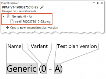 |
| 2) Stamp all relevant drawing entries. | 2) All relevant characteristics have been created. Entries with code letters are automatically recognized as word specifications, “a” and “b” for example as follows: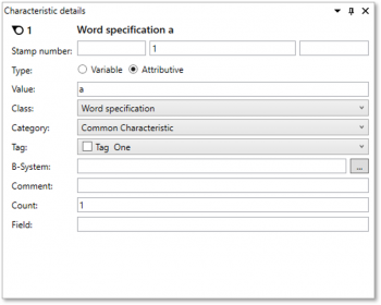 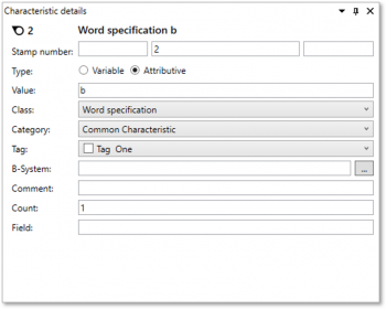 |
||
| 3) Change the characteristic properties of these characteristics so that they correspond to the first component variant for which an inspection plan is to be created. | 3) All characteristics have been created correctly. The properties of the example characteristics have been changed as follows: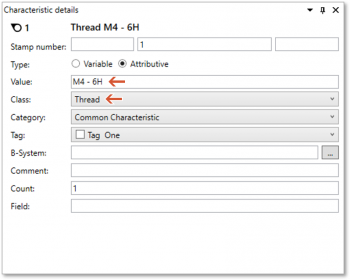 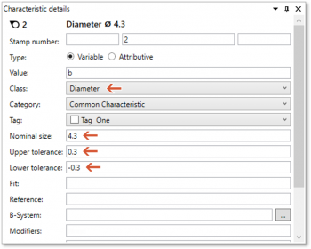 |
||
| 3 | Derive variant test plans | 1) Create the variant test plans by creating test plan versions. Name them and load the drawing sheets. | 1) The variant test plans are created, correctly named and contain the drawing sheets.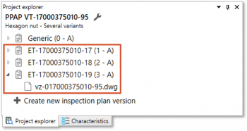 |
| 2) Now transfer the characteristics from the generic test plan to the variant test plans using the drawing comparison function. To do this, right-click on a drawing sheet in the variant test plan and choose Compare drawing sheet from the context menu. After executing the Transfer characteristics function, all characteristics should have been transferred directly. Close the drawing comparison again. See also Compare drawings (Basic version) and Compare drawings (Pro version) | 2) The variant test plans correspond to the generic test plan. | ||
| 3) Change the variable characteristics in the variant test plans according to the specifications, if necessary by deleting them. | 3) The variable characteristics of all variant test plans were compared with the specifications. | ||
| 4 | Export test plans | The test plans and stamped drawings can now be exported for each component variant. | |
| [5] | [In the course of time] Versioning test plans | When drawing changes are made, test plan versions can be derived directly from the respective variant test plan. This means that no generic inspection plan has to be created. However, it may be useful to maintain the generic inspection plan further. If a previously excluded characteristic is included again in a base planning object variant, this could be transferred from the generic test plan. | |
There are no setting options for directly influencing this function.
Go to previous page
More > Create and customize Excel templates
Go to next page
More > Terms