infra CONVERT
blue DAT • infra DAT
mdm TOOL
infra CONVERT
blue DAT • infra DAT
mdm TOOL
This is an old revision of the document!
This manual describes how to export drawing files in DWG, DXF and IGES formats (→Drawing data format) from the Creo 2.0 CAD system. The recommended settings ensure that the drawing file can be read by infra CONVERT in the best possible way.
These instructions can also be applied analogously to the following and possibly further program versions:
| Step | Action/result | |
|---|---|---|
| 1 | Open export menu | Click on Export under File > Save as. The Export setup ribbon opens. |
| 2 | Open Export settings menu | Select DWG and click on Settings.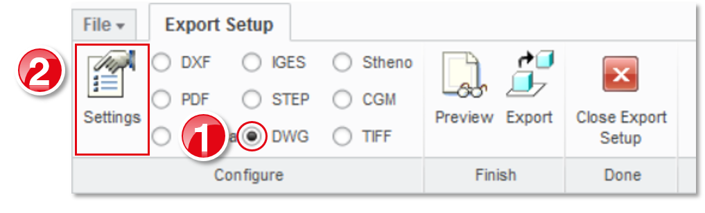 The Export environment for DWG menu opens. |
| 3 | Customize export settings | Select the following settings on the Elements, Sheets and Miscellaneous tabs. Necessary settings are marked with an arrow. Confirm the settings with OK. |
| 4 | Export drawing sheet | Click on Export. Execute the save process as usual in the file manager that opens until the end. Note You have to individually complete step four for each drawing sheet. |
| Step | Action/result | |
|---|---|---|
| 1 | Open export menu | Click on Export under File > Save as. The Export setup ribbon opens. |
| 2 | Open Export settings menu | Select DXF and click on Settings. The Export environment for DXF menu opens. |
| 3 | Customize export settings | Select the following settings on the Elements, Sheets and Miscellaneous tabs. Necessary settings are marked with an arrow.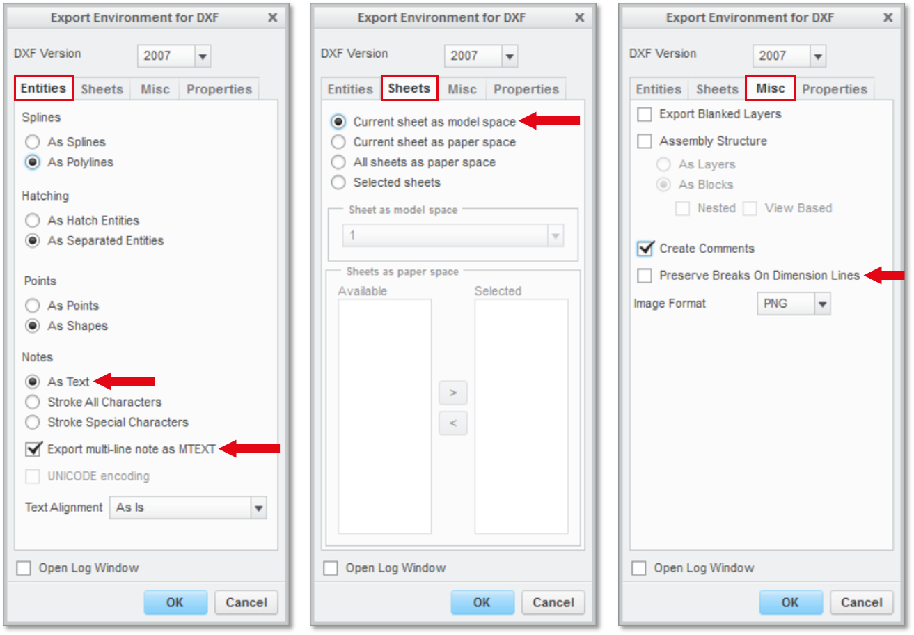 Confirm the settings with OK. |
| 4 | Export drawing sheet | Click on Export.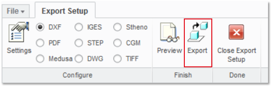 Execute the save process as usual in the file manager that opens until the end. Note You have to individually complete step four for each drawing sheet. |
| Step | Action/result | |
|---|---|---|
| 1 | Open export menu | Click on Export under File > Save as. The Export setup ribbon opens. |
| 2 | Open Export settings menu | Select IGES and click on Settings.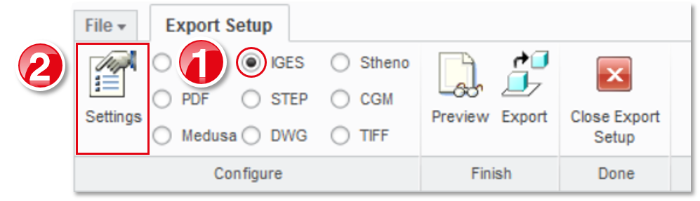 The Export environment for IGES menu opens. |
| 3 | Customize export settings | Select the following settings on the Elements, Sheets and Miscellaneous tabs. Necessary settings are marked with an arrow.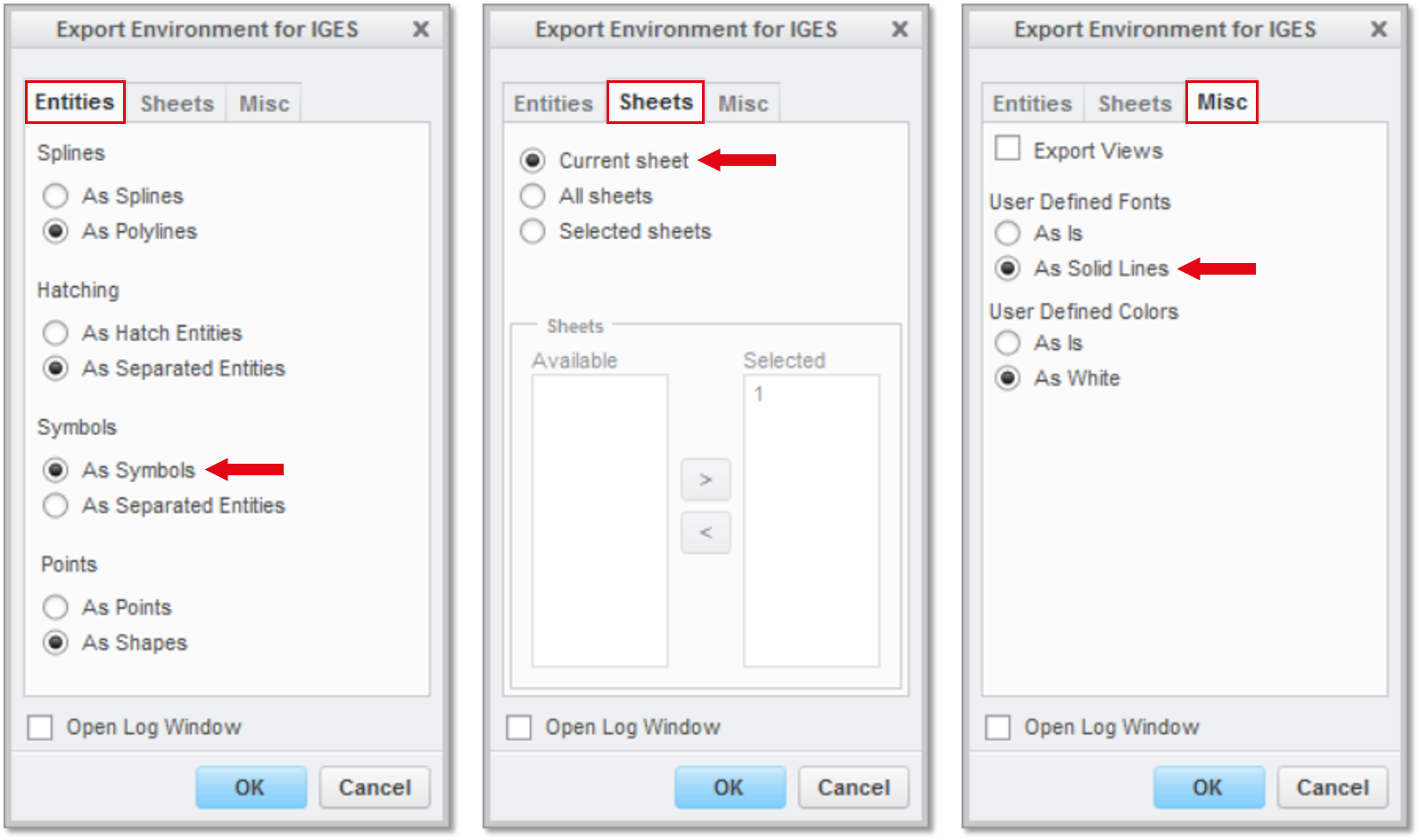 Confirm the settings with OK. |
| 4 | Export drawing sheet | Click on Export. Execute the save process as usual in the file manager that opens until the end. Note You have to individually complete step four for each drawing sheet. |
| Schritt | Aktion/Ergebnis | |
|---|---|---|
| 1 | Exportmenü öffnen | Klicken Sie unter Datei > Speichern als auf Exportieren. Es öffnet sich das Menüband “Export-Setup”. |
| 2 | Menü “Exporteinstellungen” öffnen | Wählen Sie PDF aus und klicken Sie auf Einstellungen.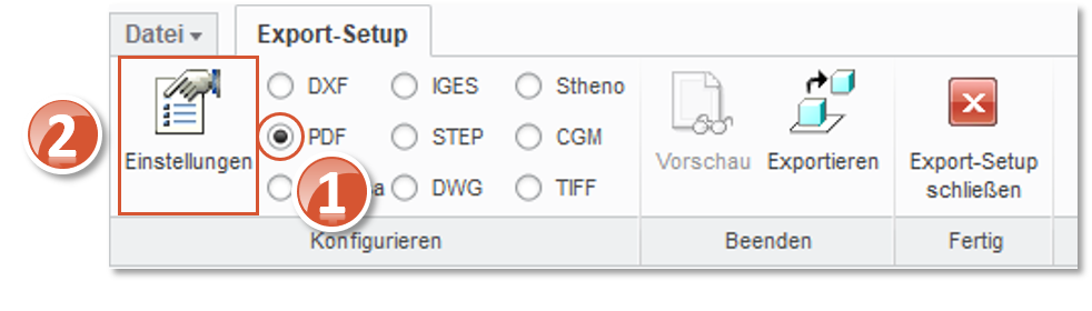 Es öffnet sich das Menü “PDF Exporteinstellungen”. |
| 3 | Exporteinstellungen anpassen | Wählen Sie auf den Registerkarten “Allgemein” und “Inhalt” die folgenden Einstellungen aus. Notwendige Einstellungen sind mit einem Pfeil markiert.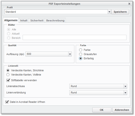 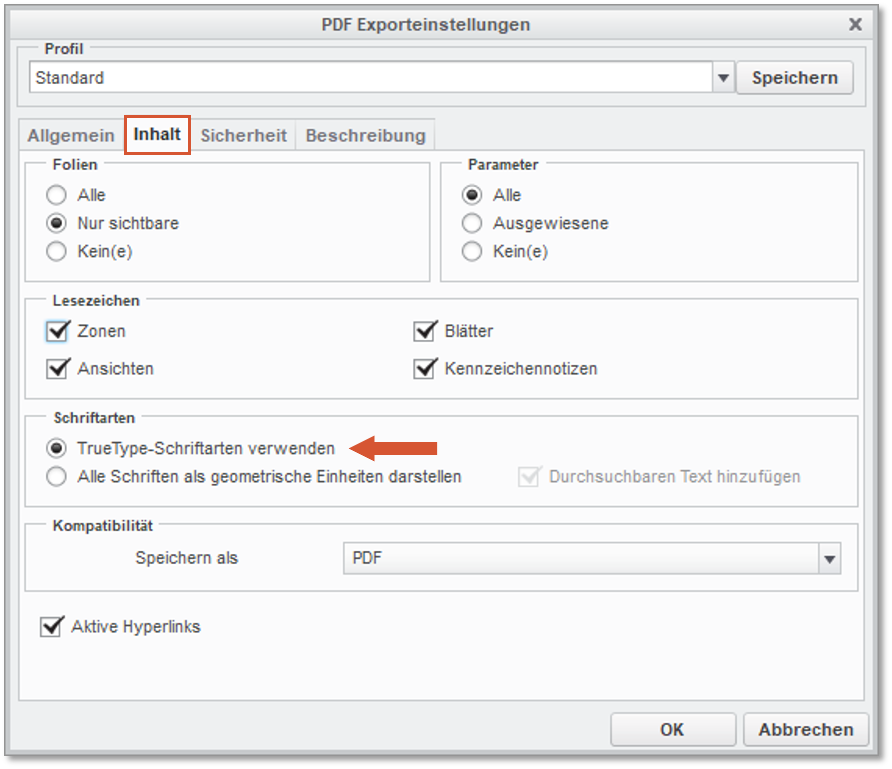 Bestätigen Sie die Einstellungen mit OK. |
| 4 | Zeichnungsblatt exportieren | Klicken Sie auf Exportieren und führen Sie den Speichervorgang wie gewohnt im sich öffnenden Dateimanager zu Ende. |