infra CONVERT
blue DAT • infra DAT
mdm TOOL
infra CONVERT
blue DAT • infra DAT
mdm TOOL
This is an old revision of the document!
The ISO GPS standard system based on DIN EN ISO 8015 regulates the language with which requirements for the geometry of a product are communicated. With an entry – constructed from “specification elements” – on the technical drawing, a specification operator in the standards system is invoked. A specification operator collates rules (“operations”) that are used to allow all the contract parties to understand the requirements of a geometric element or the relationship between geometric elements.
The principle of standard setting applies here, namely the “default principle”. Unless indicated through the addition of supplementary information in the contract agreement, the specification operator only includes default operations in a fixed order according to ISO standards. The default is chosen so that the operations approximately correspond to the most commonly used procedure and conventional understanding in practice.
In the following image, the concept is illustrated using the shaft geometric element with a nominal diameter of 20 mm as an example. At first only the defaults specification is considered, as shown on the left side. The drawing entry specifies a “linear size element” according to DIN EN ISO 14405-1 of the type “cylinder”. The default specification operator demands consideration of the “local two-point size”: All independently determined individual distances from opposite lying points must lie within the tolerance range, i.e. according to tolerance code “h9” of DIN EN ISO 286-1 at an interval of between 19.948 mm and 20 mm. Five arbitrary two-point sizes on the non-ideal surface model are represented as a geometric equivalent.* One suitable means of verification (“verification operator”) for this specification would be to carry out a check using a go/no go gauge: 1) Pass check (go): Is the maximum material size exceeded?; 2) Fail check (no-go): Is the minimum material size undershot?
* The operations of the specification operator in detail: The extracted lateral surface is assigned an ideal cylinder using the least squares method (Gaussian). The extracted lateral surface is to be cut at each height perpendicular to the derived centreline of this associated cylinder. At each cutting plane, the surface line is assigned an ideal circle according to the Gaussian method. A horizontal line is generated through each point on the surface line and the circle midpoint. If there is exactly one second intersection point with the surface line with respect to the midpoint, the distance between the two surface line intersection points is the two-point size to be matched with the interval.
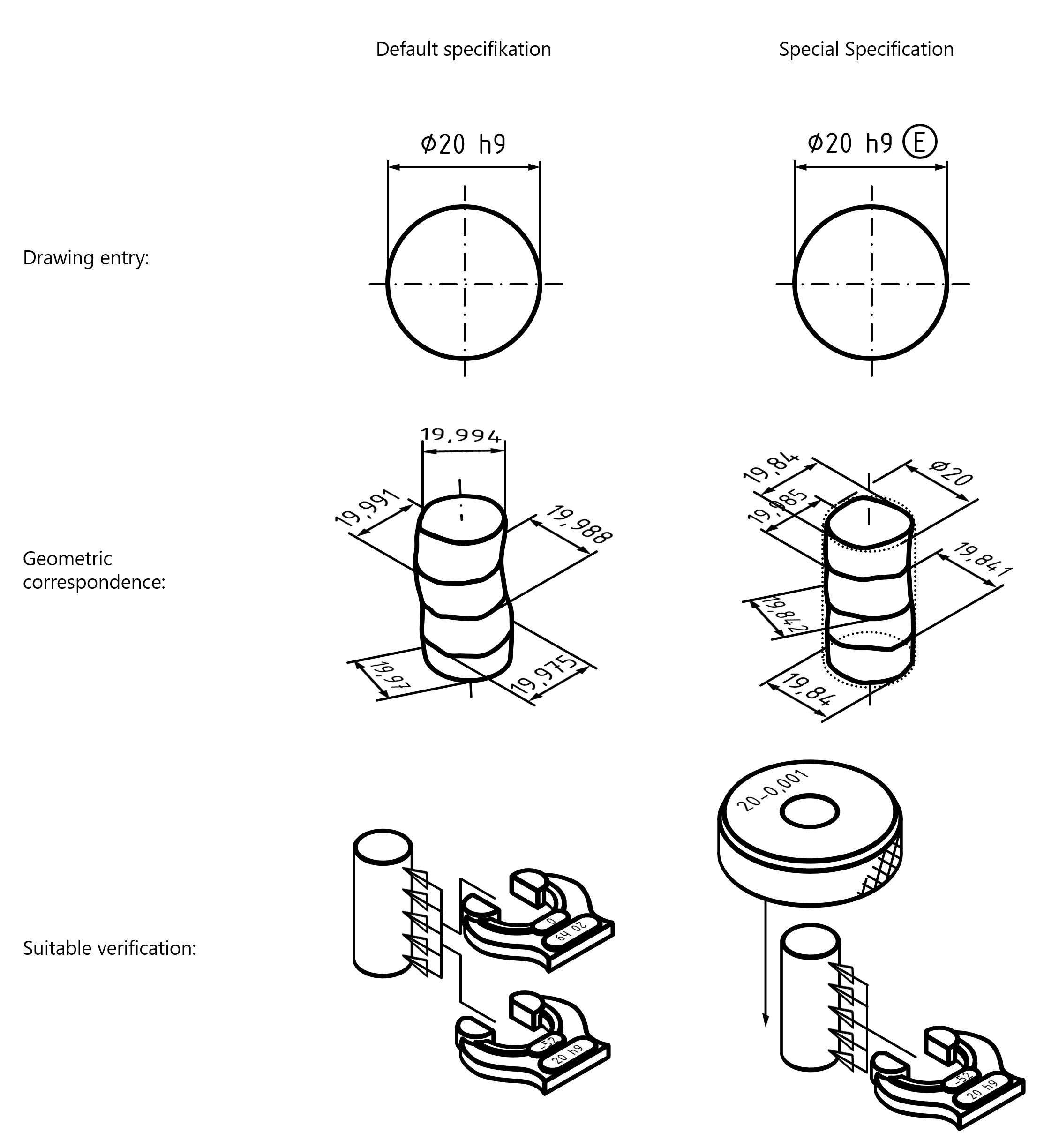
The deviation from the default setting can be identified using suitable specification modifiers (and/or abbreviations). In this way a “special specification operator” is obtained. In this example, the “E in circle” modifier symbol sets the envelope condition. The envelope condition requires that the evaluated geometry lies in an enveloping cylinder 20 mm in diameter and that all two-point sizes are greater than or equal to 19.948 mm. A suitable verification would be to test using a ring gauge or to carry out a no-go test using a go/no go gauge.
Below are examples of modifier text symbols with their meanings, such as those that can be assigned to a characteristic as property “modifiers” in infra CONVERT.
| Modifiers for linear sizes (according to DIN EN ISO 14405-1:2017-07; Characteristic classes: Length, diameter, spherical diameter) | |
|---|---|
| LP | Two-point size |
| LS | Local spherical size |
| LL | Local outer minimum material size |
| GG | Gauss method association criterion |
| GX | Maximum inscribed geometric element association criterion |
| GN | Minimum circumscribed geometric element association criterion |
| GC | Minimax association criterion |
| CC | Circumference diameter (calculated size) |
| CA | Area diameter (calculated size) |
| CV | Volume diameter (calculated size) |
| SX | Maximum rank-ordered size |
| SN | Minimum rank-ordered size |
| SA | Average rank-ordered size |
| SM | Median rank-ordered size |
| SD | Mid-range rank-ordered size |
| SR | Range of rank-ordered sizes |
| SQ | Standard deviation of sizes |
| E | Envelope requirement |
| /Length | Any limited part of the geometric element |
| ACS | Any cross-section |
| SCS | Specific fixed cross-section |
| ALS | Any longitudinal section |
| Number x | More than one geometric element Assigned as the number of repetitions of the characteristic as a property. |
| CT | Common tolerance |
| F | Condition of the free state |
| Modifiers for angular sizes (according to DIN EN ISO 14405-3:2017-07; Characteristic class: Angle) | |
|---|---|
| LC | Two-line angular size with minimax association criterion |
| LG | Two-line angular size with least squares association criterion |
| GG | Global angular size with least squares association criterion |
| GC | Global angular size with minimax association criterion |
| SX | Maximum angular size |
| SN | Minimum angular size |
| SA | Average angular size |
| SM | Median angular size |
| SD | Mid-range angular size |
| SR | Range of angular sizes |
| SQ | Standard deviation of angular size |
| SCS | Specific fixed cross-section |
| CT | Common tolerated angular size element |
| F | Condition of the free state |
| Modifiers for geometric features (according to DIN EN ISO 1101:2017-09; Characteristic classes: Geometrical tolerancing (form, orientation, location and run-out)) | |
|---|---|
| CZ | Combined zone |
| SZ | Separate zones |
| UZ | Specified tolerance zone offset |
| OZ | Unspecified linear tolerance zone offset (offset zone) |
| VA | Unspecified angular tolerance zone offset (variable angle) |
| C | Minimax (Chebyshev) feature |
| G | Least squares (Gaussian) feature |
| N | Minimum circumscribed feature |
| T | Tangent feature |
| X | Maximum inscribed feature |
| A | Derived feature |
| P | Projected tolerance zone |
| C | Minimax (Chebyshev) feature without constraint |
| CE | Minimax (Chebyshev) feature with external material constraint |
| CI | Minimax (Chebyshev) feature with internal material constraint |
| G | Least squares (Gaussian) feature without constraint |
| GE | Least squares (Gaussian) feature with external material constraint |
| GI | Least squares (Gaussian) feature with internal material constraint |
| N | Minimum circumscribed feature |
| X | Maximum inscribed feature |
| T | Total range of deviations |
| P | Peak height |
| V | Valley depth |
| Q | Standard deviation |
| UF | United feature |
| LD | Minor diameter |
| MD | Major diameter |
| PD | Pitch diameter |
| ACS | Any cross section |
| M | Maximum material requirement |
| L | Least material requirement |
| R | Reciprocity requirement |
| F | Free state condition (non-rigid parts) |
| CF | Contacting feature |
| E | Envelope requirement |