infra CONVERT
blue DAT • infra DAT
mdm TOOL
infra CONVERT
blue DAT • infra DAT
mdm TOOL
The Compare drawing views function (![]() ) function extends the characteristics transfer function (
) function extends the characteristics transfer function (![]() ).
).
See Functions > Drawings > Drawing comparison > Workflow > 2 – Transfer characteristics
It is used in the following cases:
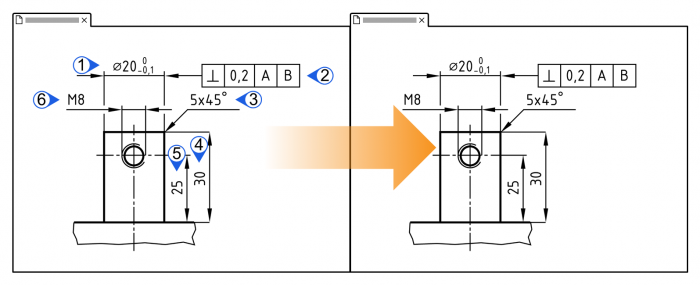
A – Only the areas visible in the drawing window are to be compared
Only drawing entries (and manually inserted stamps) that are displayed in the source drawing window should be included in the comparison.
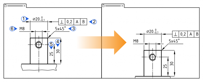
B – A shifted drawing view is to be found again in the comparison
A drawing view has shifted in the target drawing sheet in relation to the sheet origin compared to the position on the source drawing sheet. The characteristics are therefore not found again during automatic transfer (![]() ).
).
See Functions > Drawings > Drawing comparison > Workflow > 2 – Transfer characteristics
| Step | Action | Result | |
|---|---|---|---|
| 1 | Call function | 1) In the “Project overview”, right-click the target drawing sheet to whose test plan version you want to transfer characteristics.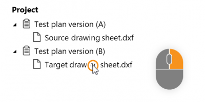 | 1) A context menu opens. |
| 2) Under the Compare drawing sheet entry ( Note A source drawing sheet must be assigned to a different test plan version than the version of the target drawing sheet. Note Up to program version 2.10.3 the source drawing sheets were selected in a separate window. | 2) The drawing comparison mode is started. The source and target drawing windows are displayed side by side. See User interface > Function windows > Drawing comparison |
||
| 2 | Fit areas in view | Fit the area to be transferred on the drawing into the drawing window. | The area is fitted. |
| [3] | [Optional] Align areas for view | If you want to compare shifted areas on the drawing sheets (use case B): 1) Un-synchronize the drawing windows by clicking Sync compare view ( | 1) The drawing windows are decoupled (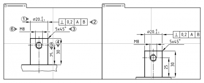 |
| 2) Align the drawing views so that the center of each drawing window is on the same point in the views, for example, on a corner of the part. | 2) Source and target drawing views are aligned with each other: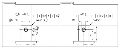 |
||
| 4 | Transfer characteristics | Click the Transfer displayed characteristics button ( | All visible characteristics are transferred.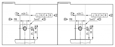 |
This function can be influenced via the following settings:
Numbering
Specify whether the characteristic number is to be retained or reassigned during merging.
See Settings > Settings > Stamp > “Number assignment during drawing comparison” group
Manually inserted characteristics
Specify whether you want manually inserted characteristics to be transferred automatically during transfer. (Available from program version 1.5.5.4.)
See Settings > Settings > Stamp > “Transfer of manually inserted characteristics during drawing comparison” group