infra CONVERT
blue DAT • infra DAT
mdm TOOL
infra CONVERT
blue DAT • infra DAT
mdm TOOL
![]()
Terms
Important terms are explained in the following.
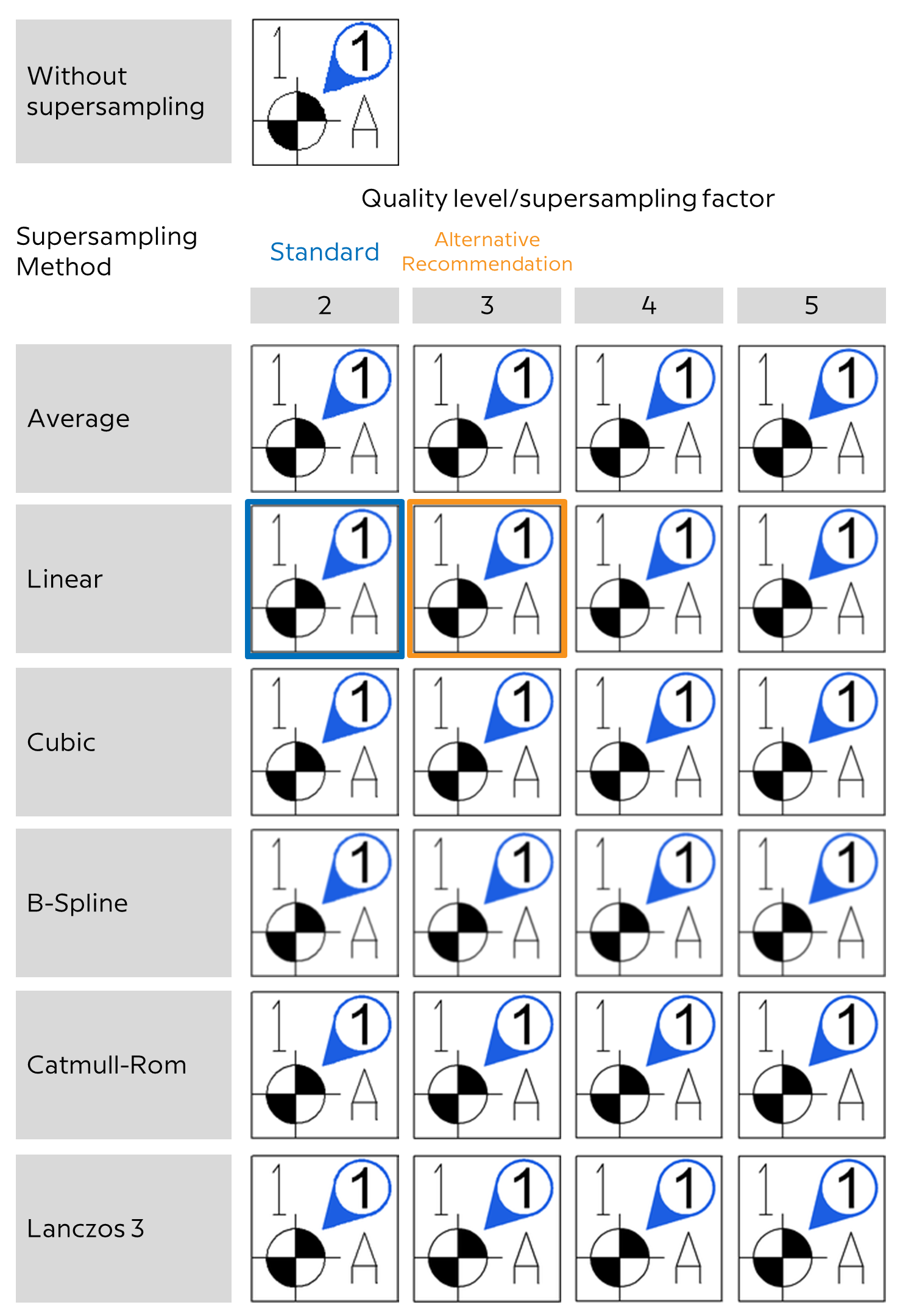
Antialiasing is applied to raster graphics to reduce unwanted staircase effects. “Supersampling”, a process for smoothing edges, is used in an intermediate stage to first generate a raster graphic with a higher resolution. The height and width are multiplied by the specified quality level. The graphic is then scaled down using the selected interpolation algorithm. This method increases the memory consumption and the runtime for the export.
The right graph shows graphic exports from infra CONVERT using the possible supersampling methods (software rendering) and with different quality levels (size of the original: 100 mm; exported as PNG with 300 dpi) Runtime and memory usage increase with the quality level and complexity of the algorithm from “average” to “Lanczos 3”.
(Click to zoom in)
→Characteristics are handled differently depending on their relevance in tests. The classification is undertaken by assigning a category. The default six categories are fixed because they are directly linked to recognition routines. They may be named differently. A further gradation of the examination relevance can be made by assigning →Tags.
Note Categories do not replace one-to-one the “feature types” used in infra - CONVERT. Characteristic types were not automatically recognized and assigned, except to a limited extent in later program versions the “Feature type 1 - Special features”. If user-defined characteristic types were defined there that do not correspond to one of the categories in infra CONVERT, you can now work with tags in this sense.

The following categories can be assigned in infra CONVERT:
| Category | Description | References |
|---|---|---|
| Standard characteristic | Characteristic that is not assigned to any of the following categories. | – |
| Special characteristic | A critical characteristic that deserves special attention. If the implementation of the characteristic does not correspond to the drawing specifications, a potential risk to functions (operational safety, interchangeability, service life, etc.) has to be expected to a great extent. Example of tagging:  | – |
| Auxiliary measurement | Measurement that is not required for the geometric determination of a part and is not considered an integral part of the contract. Example for the tagging:  | • DIN EN ISO 129-1 |
| Rough measurement | Measurement that refers to the initial state of an object. Example for the tagging:  | • DIN 406-10 |
| Theoretically accurate measurement | Measurement for indication of the geometrically ideal (theoretically precise) position or shape of the dimensioned shape element. Example for the tagging:  | • DIN EN ISO 129-1 |
| Test measurement | Measurement that must be given special attention when determining the extent of the test / test accuracy. Example for the tagging: 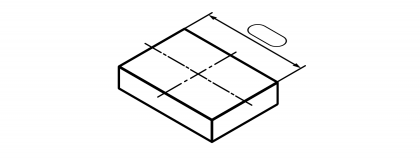 | • DIN 406-10 |
The business processes within manufacturing companies are controlled using management systems. Today, these are almost completely realized with powerful information systems. Enterprise resource planning (ERP) is the higher-level control system of a company. The efficient use of resources is planned and controlled with this, see the following figure; resources can include capital, personnel, resources, infrastructure, materials, etc.
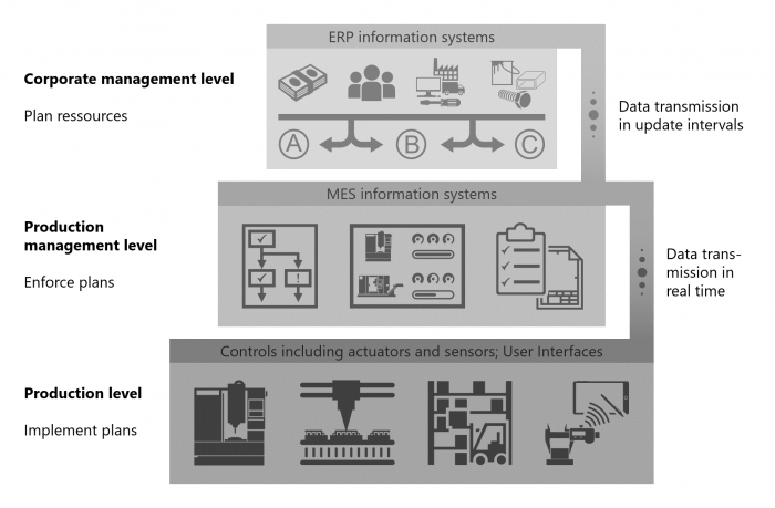
The personnel resources (management, process engineers, maintenance personnel, machine operators, etc.) and material resources (production means: manufacturing equipment, measurement devices, transportation means, packaging materials etc.) on the production level must be managed preferably in real time due to the continuously increasing complexity, speed and quality requirements of adequately efficient management information systems. The ERP system is unsuitable for process-oriented, process-specific tasks due to the requirements of company-wide data management (size, “inertia”). Task-related management systems are therefore interposed between the corporate management and production level. Collectively these are referred to as the Manufacturing Execution System (MES). MES functionalities support, among other things, detailed planning, implementation and control of production processes.
Company objectives relating to quality assurance and enhancement are today being increasingly supported by Computer Aided Quality Management (CAQ). Quality-related parameters can be analyzed and documented along the entire product life cycle in order to derive corrective measures from the results if necessary. Therefore, they are an important instrument in the MES.
Quality-relevant demands on a product (individual component, module) are essentially of a geometric and material nature. The geometry of a workpiece (or a module) is determined by the creation and modification (transformation, reproduction, referencing) of construction elements on a step by step basis (also: geometric primitives, shape elements, user defined features). Creation and modification operations require special parameters for unique identifiability, such as diameter and length of a cylinder. These are presented on the technical drawing together with other identifying information, such as material and surface specifications. The manufacturing and testing processes are based on these characteristics, as they are especially referred to in testing.
A differentiation is made between variable and attributive characteristics for test tasks here:
Variable characteristics are requirements that can be quantified. These relate to values that are associated with a tolerance and can be queried with a numerical value and a unit (→(Size-)measurements).
Attributive characteristics can only be assessed qualitatively. They are queried with fulfilled/not fulfilled or OK/NOK. Examples include “All edges deburred.”, “Pin holes drilled in composite.”, “Protection class IP 44”.
Characteristics can also be sorted by →Classes.
The specification of →characteristics in the technical drawings follows defined rules. Such rules are laid down in international and national norms, but also company publications (factory standards). Misunderstandings are avoided between the customer and the supplier when reference is made to rules of interpretation, despite a reduction in the documentation effort required. A class refers to a rule and thus specifies the context in which the characteristic properties are to be understood.
The classes listed at this point, sorted into the following groups, can be assigned in infra CONVERT. The classes relate to recognised standards (see “References” column). Unless otherwise stated, the unit of measurement always applies to tolerance limits as well.
Note Class designations and associated measurement units can be changed by your CAQ system provider or administrator, see Administrator’s Guide infra CONVERT > Configuration and Import > "CharacteristicClasses” parameter file. We would be pleased to add another class should you require it.
Note Sorting by groups will also be applied in the software in the future.
| Class | Symbol/tag | Description | References (Selection) | ID | |
|---|---|---|---|---|---|
| ELIAS | K2009 | ||||
| Length | – | Linear expansion of a geometric element or linear distance between geometric elements. Standard measurement unit Millimetres Example: 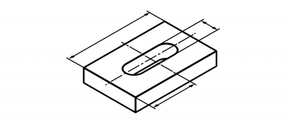 | • DIN 406-10:1992 • DIN 406-11:1992 • DIN 406-12:1992 • DIN EN ISO 286-1:2010 | 0 | 200 |
| Angle | – | Difference in the direction of two half-lines in the plane originating from a common point Standard measurement unit Degrees Example: 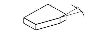 | • DIN 406-10:1992 • DIN 406-11:1992 • DIN 406-12:1992 • DIN 1315:1982 | 2 | 203 |
| Coordinates | – | Designation of the positions of points in the range. The coordinate measurements relate to a coordinate origin. Cartesian and polar coordinate systems are mostly used. Standard measurement unit Millimetres Example: 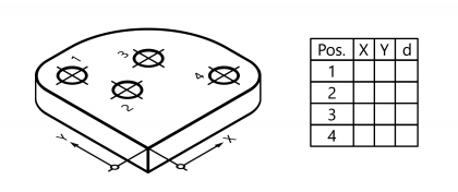 | • DIN 406-11:1992 | 65 | 117 |
| X coordinate | – | Length measurement on the X axis in a Cartesian coordinate system. Standard measurement unit Millimetres | • DIN 406-11:1992 | 57 | 120 |
| Y coordinate | – | Length measurement on the Y axis in a Cartesian coordinate system. Standard measurement unit Millimetres | • DIN 406-11:1992 | 58 | 121 |
| Z coordinate | – | Length measurement on the Z axis in a Cartesian coordinate system. Standard measurement unit Millimetres | • DIN 406-11:1992 | 59 | 122 |
| Class | Symbol/tag | Description | References (Selection) | ID | |
|---|---|---|---|---|---|
| ELIAS | K2009 | ||||
| Radius | | Distance between the centre of a circle and the circumference. Standard measurement unit Millimetres Example: 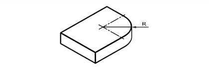 | • DIN 250:2002 • DIN 406-10:1992 • DIN 406-11:1992 | 1 | 201 |
| Spherical radius | | Distance between the centre of a sphere and the sphere surface. Standard measurement unit Millimetres Example:  | • DIN 250:2002 • DIN 406-10:1992 • DIN 406-11:1992 | 80 | 210 |
| Diameter | | Largest possible distance between two points on a circumference. Standard measurement unit Millimetres Example: 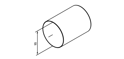 | • DIN 406-10:1992 • DIN 406-11:1992 | 2 | 202 |
| Spherical diameter | | Largest possible distance between two points on a sphere surface. Standard measurement unit Millimetres Example: 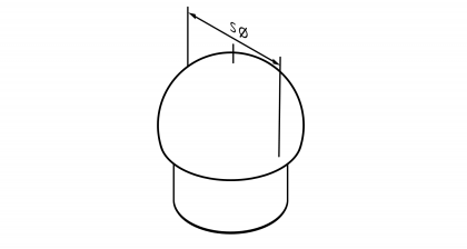 | • DIN 406-10:1992 • DIN 406-11:1992 | 81 | 210 |
| Square | | Edge length of a square shape. Standard measurement unit Millimetres Example: 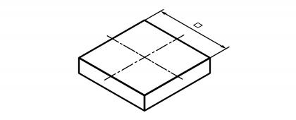 | • DIN 406-10:1992 • DIN 406-11:1992 | 82 | – |
| Width across flats | | Distance between two parallel surfaces, which is mostly used for positioning wrenches. Standard measurement unit Millimetres Example: 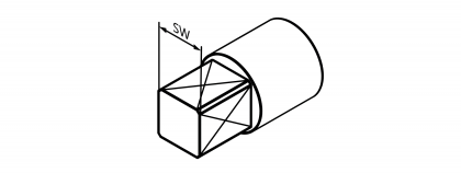 | • DIN 406-10:1992 • DIN 406-11:1992 | 83 | − |
| Slope (gradient) | | Slope ratio of an oblique line or area. Standard measurement unit – Example: 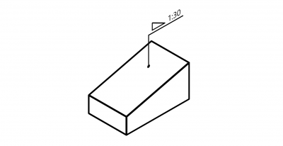 | • DIN 406-10:1992 • DIN 406-11:1992 | 84 | − |
| Slope (gradient) in % | | Slope ratio of an oblique line or area. Standard measurement unit Percent Example:  | • DIN 406-10:1992 • DIN 406-11:1992 | 85 | − |
| Tapering | | Slope ratio of a pointed or blunt cone or flat surfaces standing symmetrically at an angle to each other. Standard measurement unit – Example: 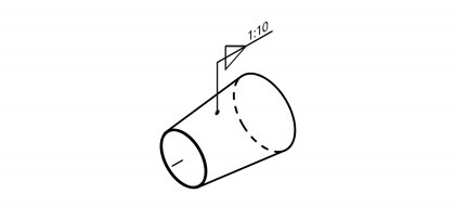 | • DIN 406-11:1992 | 86 | – |
| Tapering in % | | Slope ratio of a pointed or blunt cone or flat surfaces standing symmetrically at an angle to each other. Standard measurement unit Percent Example: 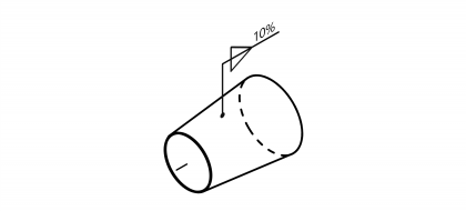 | • DIN 406-11:1992 | 87 | – |
| Cone angle | – | Point angle of a pointed or blunt cone. Standard measurement unit Degrees Example:  | – | 6 | 206 |
| Arc | | Length of an arched line. Standard measurement unit Millimetres Example: 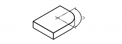 | • DIN 406-10:1992 • DIN 406-11:1992 | 88 | − |
| Ellipse large ∅ | – | Largest diameter of an ellipse. Standard measurement unit Millimetres Example: 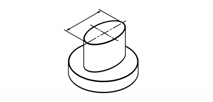 | – | 5 | 204 |
| Ellipse small ∅ | – | Smallest diameter of an ellipse. Standard measurement unit Millimetres Example: 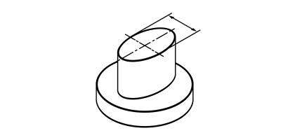 | – | 4 | 205 |
| Class | Symbol/tag | Description | References (Selection) | ID | |
|---|---|---|---|---|---|
| ELIAS | K2009 | ||||
| Straightness | | Permissible shape deviation of a line or group of lines from a reference line or reference lines. Standard measurement unit Millimetres Example: 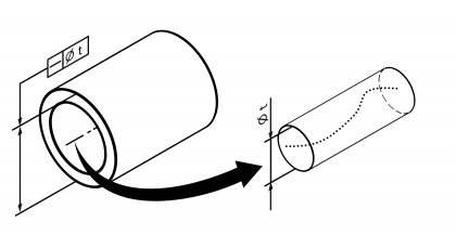 | • DIN EN ISO 1101:2014 • DIN EN ISO 12780-1:2014 | 7 | 100 |
| Straightness (shape ⌀) The tolerance range has a circular cross-section, see example. Anmerkung Available from program version 1.4.2.1 | • DIN EN ISO 1101:2014 • DIN EN ISO 12780-1:2014 | 121 | 100 | ||
| Flatness | | Permissible shape deviation of a surface from a reference plane. Standard measurement unit Millimetres Example: 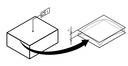 | • DIN EN ISO 1101:2014 • DIN EN ISO 12781-1:2011 | 8 | 101 |
| Roundness | | Permissible shape deviation of a circular line or group of circular lines from a reference circle or reference circles. Standard measurement unit Millimetres Example: 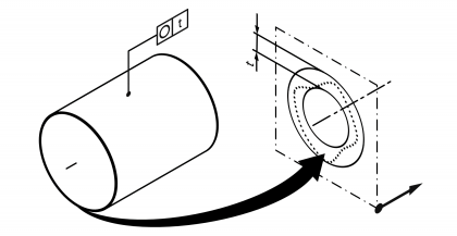 | • DIN EN ISO 1101:2014 • DIN EN ISO 12781-1:2011 | 9 | 102 |
| Cylindricity | | Permissible shape deviation of a cylindrical surface from a reference cylinder. Standard measurement unit Millimetres Example: 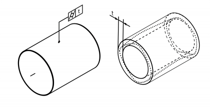 | • DIN EN ISO 1101:2014 • DIN EN ISO 12180-1:2011 | 10 | 103 |
| Line profile | | Permissible deviation of a profile line or group of profile lines from a reference line profile or from reference line profiles. Standard measurement unit Millimetres Example: 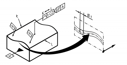 | • DIN EN ISO 1101:2014 • DIN EN ISO 1660:2013 | 11 | 104 |
| Surface profile | | Permissible deviation of a profile surface from a reference surface profile. Standard measurement unit Millimetres Example: 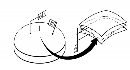 | • DIN EN ISO 1101:2014 • DIN EN ISO 1660:2013 | 12 | 105 |
| Parallelism | | Permissible deviation in direction of a line, group of lines or plane from one or several reference lines or plane(s) oriented parallel to it. Standard measurement unit Millimetres Example: 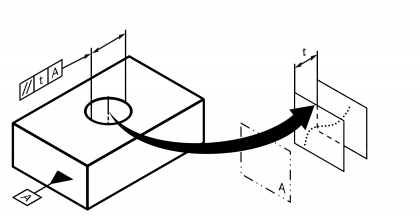 | • DIN EN ISO 1101:2014 | 13 | 108 |
| Parallelism (shape ⌀) The tolerance range has a circular cross-section. Note Available from program version 1.4.2.1 | • DIN EN ISO 1101:2014 • DIN EN ISO 12780-1:2014 | 122 | 108 | ||
| Perpendicularity | | Permissible deviation in direction of a line, group of lines or plane from one or several reference lines or plane(s) oriented perpendicular to it. Standard measurement unit Millimetres Example: 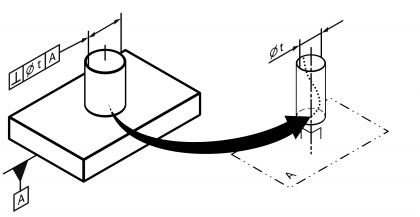 | • DIN EN ISO 1101:2014 | 14 | 107 |
| Perpendicularity (shape ⌀) The tolerance range has a circular cross-section, see example. Note Available from program version 1.4.2.1 | • DIN EN ISO 1101:2014 • DIN EN ISO 12780-1:2014 | 123 | 107 | ||
| Inclination | | Permissible deviation in direction of a line, group of lines or plane from one or several reference lines or plane(s) oriented angular (but not perpendicular) to it. Standard measurement unit Millimetres Example: 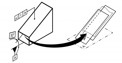 | • DIN EN ISO 1101:2014 | 15 | 106 |
| Inclination (shape ⌀) The tolerance range has a circular cross-section. Note Available from program version 1.4.2.1 | • DIN EN ISO 1101:2014 • DIN EN ISO 12780-1:2014 | 124 | 106 | ||
| Position | | Permissible positional deviation of a point, axis or plane from a reference point, reference line or plane positioned to it. Standard measurement unit Millimetres Example: 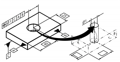 | • DIN EN ISO 1101:2014 • DIN EN ISO 5458:1999 | 22 | 109 |
| Position (shape ⌀) The tolerance range has a circular cross-section, see example. Note Available from program version 1.4.2.1 | • DIN EN ISO 1101:2014 • DIN EN ISO 12780-1:2014 | 125 | 109 | ||
| Position (shape S⌀) The tolerance range has a circular cross-section. Note Available from program version 1.4.2.1 | • DIN EN ISO 1101:2014 • DIN EN ISO 12780-1:2014 | 126 | 109 | ||
| Concentricity | | Permissible positional deviation of a point from a reference point concentric to it. Standard measurement unit Millimetres Example:  | • DIN EN ISO 1101:2014 | 21 | 110 |
| Concentricity (shape ⌀) The tolerance range has a circular cross-section, see example. Note Available from program version 1.4.2.1 | • DIN EN ISO 1101:2014 • DIN EN ISO 12780-1:2014 | 128 | 110 | ||
| Coaxiality | | Permissible positional deviation of straight line from a straight reference line coaxial to it. Standard measurement unit Millimetres Example:  | • DIN EN ISO 1101:2014 | 89 | 663 |
| Coaxiality (shape ⌀) The tolerance range has a circular cross-section, see example. Note Available from program version 1.4.2.1 | • DIN EN ISO 1101:2014 • DIN EN ISO 12780-1:2014 | 127 | 110 | ||
| Symmetry | | Permissible positional deviation of a point, group of points, straight line or plane from one or several reference point(s) or plane(s) lying symmetrical to it. Standard measurement unit Millimetres Example:  | • DIN EN ISO 1101:2014 | 20 | 111 |
| Radial concentric run-out | | Permissible radial running deviation of a circular line or group of circular lines to one or several reference circle(s) that lies coaxial to it. Standard measurement unit Millimetres Example: 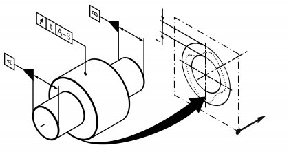 | • DIN EN ISO 1101:2014 | 16 | 112 |
| Axial concentric run-out | | Permissible axial running deviation of a circular line or group of circular lines to one or several reference circle(s) that lies coaxial to it. Also called lateral run. Standard measurement unit Millimetres Example: 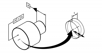 | • DIN EN ISO 1101:2014 | 17 | 118 |
| Radial total concentric run-out | | Permissible radial running deviation of a rotational surface to a rotational surface that lies coaxial to it. Standard measurement unit Millimetres Example: 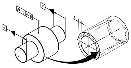 | • DIN EN ISO 1101:2014 | 18 | 113 |
| Axial total concentric run-out | | Permissible axial running deviation of a plane or rotational surface to a plane or rotational surface that lies coaxial to it. Also called total lateral run. Standard measurement unit Millimetres Example: 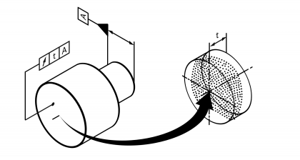 | • DIN EN ISO 1101:2014 | 19 | − |
| Class | Symbol/tag | Description | References (Selection) | ID | |
|---|---|---|---|---|---|
| ELIAS | K2009 | ||||
| Thread | – | Fastening or transmission threads of various systems, e.g. metric ISO thread or inch ISO pipe thread. Standard measurement unit – Example: 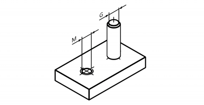 | • DIN 202:1999 • DIN ISO 6410:1993 | 38 | − |
| Class | Symbol/tag | Description | References (Selection) | ID | |
|---|---|---|---|---|---|
| ELIAS | K2009 | ||||
| Pitch diameter | – | Diameter of the pitch circle / cylinder of a gearwheel. Standard measurement unit Millimetres Example:  | • DIN 3966-1:1978 | 90 | − |
| Root circle diameter | – | Diameter of a gearwheel in root height of the teeth. Standard measurement unit Millimetres Example:  | • DIN 3966-1:1978 | 91 | 612 |
| Tip circle diameter | – | Diameter of a gearwheel in tip height of the teeth. Standard measurement unit Millimetres Example:  | • DIN 3966-1:1978 • DIN 3966-2:1978 | 92 | 610 |
| Tooth thickness | – | Thickness of a gearwheel tooth on the pitch circle / pitch cylinder. Standard measurement unit Millimetres Example:  | • DIN 3966-1:1978 • DIN 3966-2:1978 | 120 | 211 |
| Tooth width | – | Tooth width over a number of k measurement teeth or measurement gaps. Standard measurement unit Millimetres Example: 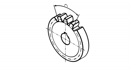 | • DIN 3966-1:1978 • DIN 3966-2:1978 | 94 | 216 |
| Gap width | – | Tooth gap width on the pitch circle / pitch cylinder. Standard measurement unit Millimetres Example: 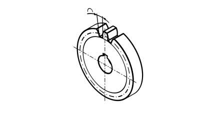 | • DIN 3966-1:1978 • DIN 3966-2:1978 | 95 | 617 |
| Class | Symbol/tag | Description | References (Selection) | ID | |
|---|---|---|---|---|---|
| Edge with indeterminate shape | | Workpiece edge without a precisely determined shape. A deviation from an ideal geometric shape is permissible depending on burr and breakage direction as well as edge dimension. Standard measurement unit Millimetres Example:  | • DIN ISO 13715:2000 | 34 | − |
| Chamfer | – | Workpiece edge in the form of a specific, chamfered surface. Example:  | • DIN 406-10:1992 • DIN 406-11:1992 | 33 | − |
| Curve | – | Workpiece edge in the form of a specific, rounded surface. Standard measurement unit Millimetres Example: 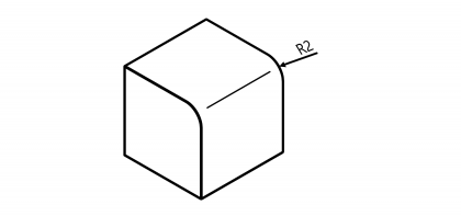 | • DIN 406-10:1992 • DIN 406-11:1992 | 35 | − |
| Edge | – | Workpiece edge. Specification without reference to a standard. Standard measurement unit Millimeter (mm) | − | 36 | − |
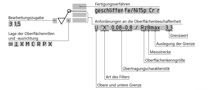
Structure of drawing entries
The requirements of surface properties are entered into the drawing using a graphical symbol. The position and structure of the fields for individual entries is determined as follows (cf. DIN EN ISO 1302:2002-06):
| Class | Symbol/tag | Description | References (Selection) | ID | |
|---|---|---|---|---|---|
| ELIAS | K2009 | ||||
| Smoothing depth (peak) | | Vertical parameter of the roughness profile. Height of the largest profile peak within the measuring section ln. Standard measurement unit Micrometres 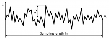 | • DIN EN ISO 4287:2010 • DIN EN ISO 4288:1998 • DIN EN ISO 1302:2002 | 96 | – |
| Smoothing depth (valley) | | Vertical parameter of the roughness profile. Depth of the largest profile valley within the measuring section. Standard measurement unit Micrometres 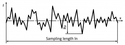 | • DIN EN ISO 4287:2010 • DIN EN ISO 4288:1998 • DIN EN ISO 1302:2002 | 97 | – |
| Average roughness depth | | Vertical parameter of the roughness profile. Sum of the height of the largest profile peak and the depth of the largest profile valley within a single measurement section. Standard measurement unit Micrometres 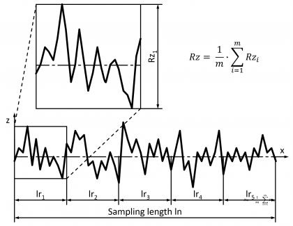 | • DIN EN ISO 4287:2010 • DIN EN ISO 4288:1998 • DIN EN ISO 1302:2002 | 23 | 150 |
| Maximum average roughness depth |  | This parameter is a variation of the regular requirement for the average roughness depth. The specified variable is not to be interpreted with the 16 % rule, but with the maximum value rule. “Rmax” is also commonly used as an indicator. Standard measurement unit Micrometres | • DIN EN ISO 4287:2010 • DIN EN ISO 4288:1998 • DIN EN ISO 1302:2002 | 31 | 158 |
| Average profile element height | | Vertical parameter of the roughness profile. Average value of the height of the profile elements within a single measuring section. A profile element is formed based on a consecutive profile valley and a profile peak. Standard measurement unit Micrometres 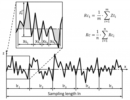 | • DIN EN ISO 4287:2010 • DIN EN ISO 4288:1998 • DIN EN ISO 1302:2002 | 98 | – |
| Total height | | Vertical parameter of the primary profile. Sum of the height of the largest profile peak and the depth of the largest profile valley within the section. Standard measurement unit Micrometres 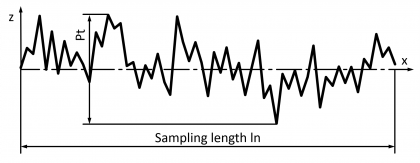 | • DIN EN ISO 4287:2010 • DIN EN ISO 4288:1998 • DIN EN ISO 1302:2002 | 26 | 153 |
| Total height | | Vertical parameter of the roughness profile. Sum of the height of the largest profile peak and the depth of the largest profile valley within the section. Standard measurement unit Micrometres 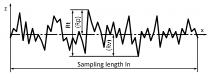 | • DIN EN ISO 4287:2010 • DIN EN ISO 4288:1998 • DIN EN ISO 1302:2002 | 93 | – |
| Total height | | Vertical parameter of the waviness profile. Sum of the height of the largest profile peak and the depth of the largest profile valley within the section. Standard measurement unit Micrometres 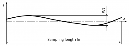 | • DIN EN ISO 4287:2010 • DIN EN ISO 4288:1998 • DIN EN ISO 1302:2002 | 30 | 157 |
| Arithmetic average roughness value | | Vertical parameter of the roughness profile. Arithmetic average of the sums of the amplitude values within a single measuring section. Standard measurement unit Micrometres 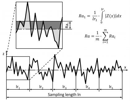 | • DIN EN ISO 4287:2010 • DIN EN ISO 4288:1998 • DIN EN ISO 1302:2002 | 25 | 152 |
| Quadratic average roughness value | | Vertical parameter of the roughness profile. Quadratic average of the amplitude values within a single measuring section. Standard measurement unit Micrometres 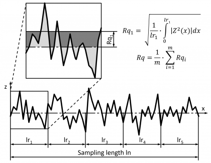 | • DIN EN ISO 4287:2010 • DIN EN ISO 4288:1998 • DIN EN ISO 1302:2002 | 99 | – |
| Profile skew | | Vertical parameter of the roughness profile. Measurement for the asymmetry of the amplitude density curve within a single measuring section. The amplitude density curve reflects the amplitude part in each horizontal sectional plane. Standard measurement unit Micrometres 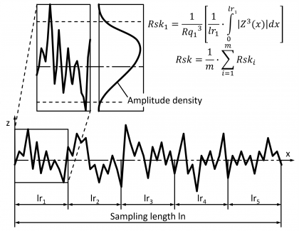 | • DIN EN ISO 4287:2010 • DIN EN ISO 4288:1998 • DIN EN ISO 1302:2002 | 100 | – |
| Profile steepness | | Vertical parameter of the roughness profile. Measurement for the steepness of the amplitude density curve within a single measuring section. The amplitude density curve reflects the amplitude part in each horizontal sectional plane. Standard measurement unit Micrometres  | • DIN EN ISO 4287:2010 • DIN EN ISO 4288:1998 • DIN EN ISO 1302:2002 | 101 | – |
| Average groove width | | Horizontal parameter of the roughness profile. Average value of the profile elements within a single measuring section. Standard measurement unit Micrometres 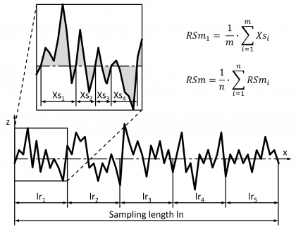 | • DIN EN ISO 4287:2010 • DIN EN ISO 4288:1998 • DIN EN ISO 1302:2002 | 102 | – |
| Peak count | | Horizontal parameter of the roughness profile. Number of average widths of the profile elements in a predefined length, standard 10mm. Standard measurement unit – 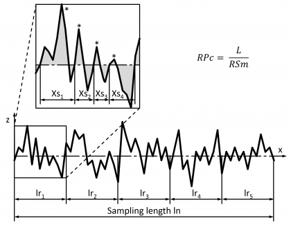 | • DIN EN ISO 4287:2010 • DIN EN ISO 4288:1998 • DIN EN ISO 1302:2002 | 103 | – |
| Average profile gradient | | Mixed (vertical and horizontal) parameter of the roughness profile. Quadratic average of the local profile gradient within a single measuring section. Standard measurement unit Micrometres 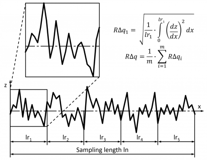 | • DIN EN ISO 4287:2010 • DIN EN ISO 4288:1998 • DIN EN ISO 1302:2002 | 104 | – |
| Material share | | Parameter from the Abbott-Firestone curve (AF curve) of the primary profile. Material share in a cutting line height relative to the share in a reference cutting line height. The AF curve reflects the cumulative frequency of the amplitude values within a measuring section. Standard measurement unit Percent | • DIN EN ISO 4287:2010 • DIN EN ISO 4288:1998 • DIN EN ISO 1302:2002 | 70 | 160 |
| Material share | | Parameter from the Abbott-Firestone curve (AF curve) of the roughness profile. Material share in a cutting line height relative to the share in a reference cutting line height. The AF curve reflects the cumulative frequency of the amplitude values within a measuring section. Standard measurement unit Percent 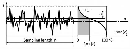 | • DIN EN ISO 4287:2010 • DIN EN ISO 4288:1998 • DIN EN ISO 1302:2002 | 105 | 193 |
| Core roughness depth | | Parameter of the roughness core profile. Total height of the roughness core profile within the measuring section. The roughness core profile is the roughness profile without projecting peaks and deep valleys. Standard measurement unit Micrometres  | • DIN EN ISO 13565-2:1998 • DIN EN ISO 1302:2002 | 27 | 154 |
| Smallest material share | | Parameter of the roughness core profile. Material share in percent at the level of the cutting line, which separates the projecting peaks from the roughness core profile. The roughness core profile is the roughness profile without projecting peaks and deep valleys. Standard measurement unit Percent 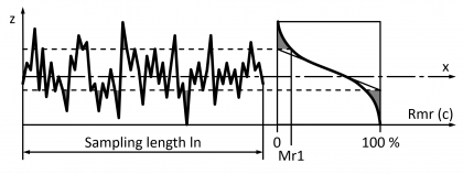 | • DIN EN ISO 13565-2:1998 • DIN EN ISO 1302:2002 | 71 | 161 |
| Largest material share | | Parameter of the roughness core profile. Material share in percent at the level of the cutting line, which separates the deep valleys from the roughness core profile. The roughness core profile is the roughness profile without projecting peaks and deep valleys. Standard measurement unit Percent 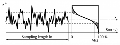 | • DIN EN ISO 13565-2:1998 • DIN EN ISO 1302:2002 | 72 | 162 |
| Reduced peak height | | Average height of the projecting peaks above the roughness core profile. The roughness core profile is the roughness profile without projecting peaks and deep valleys. Standard measurement unit Micrometres 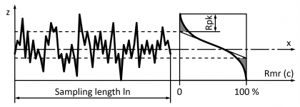 | • DIN EN ISO 13565-2:1998 • DIN EN ISO 1302:2002 | 28 | 155 |
| Reduced groove depth | | Average depth of the profile valleys below the roughness core profile. The roughness core profile is the roughness profile without projecting peaks and deep valleys. Standard measurement unit Micrometres 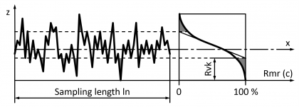 | • DIN EN ISO 13565-2:1998 • DIN EN ISO 1302:2002 | 29 | 156 |
| Base roughness depth | | Vertical parameter of the roughness profile. Amplitude value of the third highest profile peak from the third largest profile valley. Standard measurement unit Micrometres 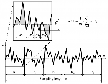 | Not officially standardised. | 32 | 159 |
| Additional surface specifications | – | Machining allowance, position and orientation of surface grooves. Standard measurement unit – | • DIN EN ISO 1302:2002 | 118 | – |
| Layer thickness | – | Material thickness of one or more coatings over a surface. Standard measurement unit Millimetres | – | 64 | 260 |
| Class | Symbol/tag | Description | References (Selection) | ID | |
|---|---|---|---|---|---|
| ELIAS | K2009 | ||||
| Material | – | Material, identifiable by a unique abbreviation or number. Standard measurement unit – | – | 74 | – |
| Volumes in mm³ | – | Spatial contents of a geometric body. Standard measurement unit Cubic millimetres | – | 106 | 270 |
| Volumes in cm³ | – | Spatial contents of a geometric body. Standard measurement unit Cubic centimetres | – | 107 | 270 |
| Volumes in dm³ | – | Spatial contents of a geometric body. Standard measurement unit Cubic decimetres | – | 108 | 270 |
| Volumes in m³ | – | Spatial contents of a geometric body. Standard measurement unit Cubic metres | – | 65 | 270 |
| Mass in g | – | Property of a body specified by density and volume. Standard measurement unit Grams | 109 | 280 | |
| Mass in kg | – | Property of a body specified by density and volume. Standard measurement unit Kilograms | 66 | 280 | |
| Hardness | – | Hardness of a material. No defined parameters. Standard measurement unit – | – | 110 | 285 |
| Brinell hardness | | Parameter for the hardness of a material, ascertained in the Brinell hardness test. The parameter is determined from the impression diameter of a carbide ball (loaded with the test force F) at a diameter D in the sample surface. Standard measurement unit – 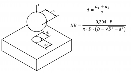 | • DIN EN ISO 6506-1:2015 | 39 | – |
| Rockwell hardness | | Parameter for the hardness of a material, ascertained in the Rockwell hardness test (hardness scale A). The parameter is determined from the penetration depth h of a diamond cone with the cone angle 120°, which is generated by the additional force F1 (the penetration depth generated by the advance test force F0 that is applied simultaneously is deducted from the total penetration depth here). Standard measurement unit –  | • DIN EN ISO 6508-1:2016 | 40 | – |
| Rockwell hardness | | Parameter for the hardness of a material, ascertained in the Rockwell hardness test (hardness scale B). The parameter is determined from the penetration depth h of a carbide ball with the diameter D, which is generated by the additional force F1 (the penetration depth generated by the advance test force F0 that is applied simultaneously is deducted from the total penetration depth here). Standard measurement unit – 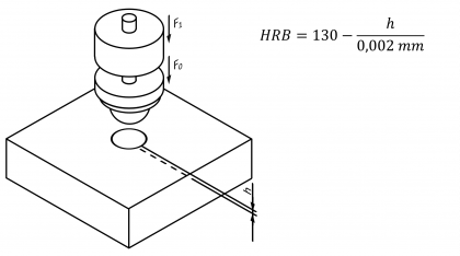 | • DIN EN ISO 6508-1:2016 | 41 | – |
| Rockwell hardness | | Parameter for the hardness of a material, ascertained in the Rockwell hardness test (hardness scale C). The parameter is determined from the penetration depth h of a diamond cone with the cone angle 120°, which is generated by the additional force F1 (the penetration depth generated by the advance test force F0 that is applied simultaneously is deducted from the total penetration depth here). Standard measurement unit – 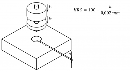 | • DIN EN ISO 6508-1:2016 | 42 | – |
| Rockwell hardness | | Parameter for the hardness of a material, ascertained in the Rockwell hardness test (hardness scale F). The parameter is determined from the penetration depth h of a carbide ball with the diameter D, which is generated by the additional force F1 (the penetration depth generated by the advance test force F0 that is applied simultaneously is deducted from the total penetration depth here). Standard measurement unit – 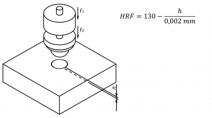 | • DIN EN ISO 6508-1:2016 | 43 | – |
| Vickers hardness | | Parameter for the hardness of a material, ascertained in the Vickers hardness test. The parameter is determined from the impression diagonal diameter of a diamond pyramid (with a quadratic base and a point angle of 136°), which is loaded with the test force F, in the sample surface Standard measurement unit – 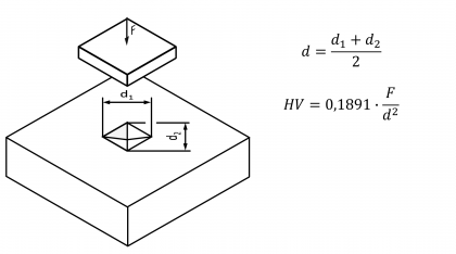 | • DIN EN ISO 6507-1 | 44 | – |
| Martens hardness | | Parameter for the hardness of a material, ascertained in the penetration test. The parameter is determined from the values of the force-penetration-depth curve, which is recorded during the penetration of a test body (various shapes and materials are permissible) under the force F. Standard measurement unit – 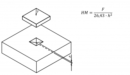 | • DIN EN ISO 14577-1:2015 | 45 | – |
| Ball indentation hardness | | Parameter for the hardness of plastics, ascertained in the ball indentation test. The parameter corresponds to the quotient on the test force F1 (in N) and the spherical cap surface A (in mm²) of the indentation after a defined time (the surface is calculated from the penetration depth h and the ball diameter. The penetration depth h is measured after the advance test force F0 is applied). Standard measurement unit – 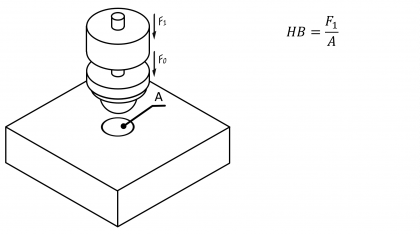 | • DIN EN ISO 2039-1:2003 | 46 | – |
| Shore hardness | | Parameter for the hardness of plastics, ascertained in the Shore hardness test (type A durometer). Standard measurement unit – 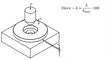 | • DIN EN ISO 868:2003 | 47 | – |
| Shore hardness | | Parameter for the hardness of plastics, ascertained in the Shore hardness test (type D durometer). Standard measurement unit – 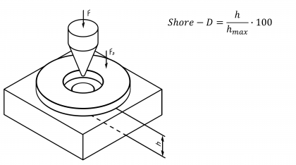 | • DIN EN ISO 868:2003 | 48 | – |
| Proof strength in MPa | | Material parameter of a tensile test specimen determined in a tensile test with a continuous stress-strain curve. It indicates the stress R, which occurs in relation to the (initial) cross section of the specimen S0 at 0.1% plastic strain e. Standard measurement unit Megapascals 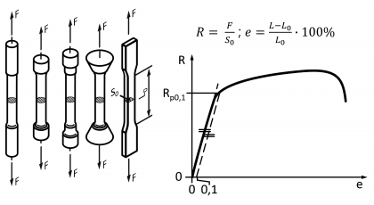 | • DIN EN ISO 6892-1:2017 | 49 | – |
| Proof strength in MPa | | Material parameter of a tensile test specimen determined in a tensile test with a continuous stress-strain curve. It indicates the stress R, which occurs in relation to the (initial) cross section of the specimen S0 at 0.2% plastic strain e. Standard measurement unit Megapascals 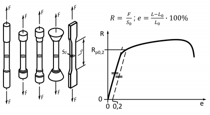 | • DIN EN ISO 6892-1:2017 | 50 | – |
| Proof strength in MPa | | Material parameter of a tensile test specimen determined in a tensile test with a continuous stress-strain curve. It indicates the stress R, which occurs in relation to the (initial)cross section of the specimen S0 at 1.0% plastic strain e. Standard measurement unit Megapascals 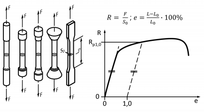 | • DIN EN ISO 6892-1:2017 | 51 | – |
| Yield strength in MPa | | Material parameter of a metallic tensile test specimen determined in a tensile test with a pronounced stress-strain curve. It indicates the highest stress R, at which a first significant drop in the stress is encountered. Standard measurement unit Megapascals  | • DIN EN ISO 6892-1:2017 | 52 | – |
| Yield strength in MPa | | Material parameter of a metallic tensile test specimen determined in a tensile test with a pronounced stress-strain curve. It indicates the lowest stress R during the plastic flow (Lüders strain) Standard measurement unit Megapascals 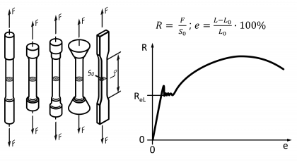 | • DIN EN ISO 6892-1:2017 | 53 | – |
| Tensile strength in MPa | | Material parameter of a tensile test specimen determined in a tensile test with a pronounced or continuous stress-strain curve. It indicates the stress R at maximum force absorption. Example of a pronounced stress-strain curve: 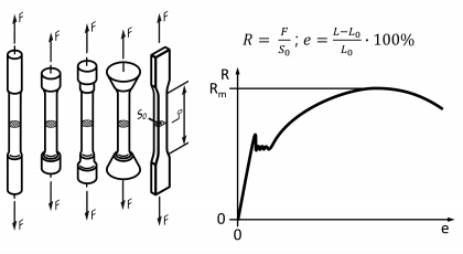 Standard measurement unit Megapascals | • DIN EN ISO 6892-1:2017 | 54 | – |
| Elongation at break in % | | Material parameter of a tensile test specimen determined in a tensile test with a pronounced or continuous stress-strain curve. It indicates the plastic specimen strain e in %, at which the sample breaks. Example of a pronounced stress-strain curve: 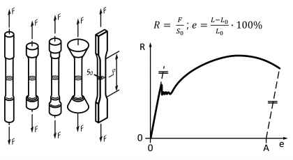 Standard measurement unit Percent | • DIN EN ISO 6892-1:2017 | 55 | – |
| Notch impact energy | – | In a standardized procedure, e.g. the Charpy test, determined material characteristic. It indicates the impact energy consumed in the fracture of a mostly notched specimen. Standard measurement unit Joule Simplified example of the Charpy impact test using a pendulum impact tester and a V-notched sample (K = consumed impact energy, Kp1 = potential initial energy, Kp2 = residual energy): 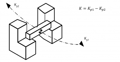 Note Available from program version 1.2.0.32 | • DIN EN ISO 148-1 | 129 | – |
| Class | Symbol/tag | Description | References (Selection) | ID | |
|---|---|---|---|---|---|
| ELIAS | K2009 | ||||
| Time in s | – | Time period between two events. Standard measurement unit Seconds | – | 111 | 800 |
| Time in min | – | Time period between two events. Standard measurement unit Minutes | – | 112 | 800 |
| Time in h | – | Time period between two events. Standard measurement unit Hours | – | 113 | 800 |
| Force in N | – | External influence on a body that can deform and accelerate it. Standard measurement unit Newtons | – | 67 | 282 |
| Force in kN | – | External influence on a body that can deform and accelerate it. Standard measurement unit Kilonewtons | – | 67 | 282 |
| Torque in Nm | – | External influence on torsion, determined by the product of the impacting force and the radial distance from the centre. Standard measurement unit Newton metres | • DIN 6790-1:2008 | 37 | 301 |
| Pressure in bar | – | Normal stress acting equally in all spatial directions. Standard measurement unit Bar | – | 63 | 255 |
| Temperature in °C | – | Temperature, specified in degrees Celsius. Standard measurement unit Degrees Celsius | – | 61 | 250 |
| Temperature in °F | – | Temperature, specified in degrees Fahrenheit. Standard measurement unit Degrees Fahrenheit | – | 62 | 251 |
| Spring rate in N/m | – | Parameter for the rigidity of a spring, specified as the ratio of the acting force to deflection. Standard measurement unit Newtons per metre | – | 60 | 220 |
| Rotational speed in 1/s | – | Angular velocity of a rotating body, specified in revolutions or angles per unit of time. Standard measurement unit Per second | • DIN ISO 21940-2:2017 | 115 | 350 |
| Rotational speed in 1/min | – | Angular velocity of a rotating body, specified in revolutions or angles per unit of time. Standard measurement unit Per minute | • DIN ISO 21940-2:2017 | 116 | 350 |
| Imbalance | – | Deviation of a rotating body caused by centrifugal force. Standard measurement unit – | – | 69 | 300 |
| Viscosity | – | Viscosity of a liquid or gas. Standard measurement unit – | – | 68 | 290 |
| Class | Symbol/tag | Description | References (Selection) | ID | |
|---|---|---|---|---|---|
| ELIAS | K2009 | ||||
| Production process | – | Process of manufacturing workpieces by attaining the initial forms from a formless state, changing these forms, and altering material properties. Standard measurement unit – | • DIN EN ISO 6892-1:2017 | 117 | – |
| Text entry | – | Drawing entry in text form (characters, symbols, words, word groups, paragraphs, sentences, etc.) with or without direct reference to a characteristic. Standard measurement unit – | • DIN 6790-1:2008 | 75 | 310 |
| Welding joint | – | Specification of the requirements for a seam to be produced by welding, e.g. As type, thickness, length, quality, surface treatment, welding filler, testing requirements. Standard measurement unit – Note Available from program version 1.2.0.32 | – | 130 | – |
| Solder joint | – | Specification of the requirements for a seam to be produced by soldering, e.g. type, thickness, length, quality, surface treatment, solder, test requirements. Standard measurement unit – Note Available from program version 1.2.0.32 | – | 133 | – |
| Marking | – | Fixed or detachable with a workpiece or assembly to be connected in plain text or machine-readable information. Standard measurement unit – Note Available from program version 1.2.0.32 | – | 131 | – |
| Function | – | Task to be performed by the workpiece or assembly. Standard measurement unit – Note Available from program version 1.2.0.32 | – | 132 | – |
| Undefined | – | No class is defined. Standard measurement unit – Not Available from program version 1.2.0.32 | – | -1 | 0 |
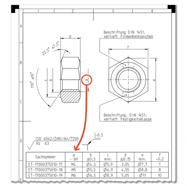
A →technical drawing is referred to as a collective drawing if several variants of a similar component or assembly, each with its own part number, are grouped together in this document. (see DIN 30:2002-12)
Usually only one of the component variants or a generic component, which contains all properties in one characteristic, is displayed graphically. The variable properties are indicated with a code letter (also: “dimension letter”) and called up in a table.
A Technical drawing is part of the technical product documentation. It includes technical information, which is usually displayed graphically on an information medium to scale as well as two-dimensional and based on the agreed rules. (see DIN EN ISO 10209:2012)
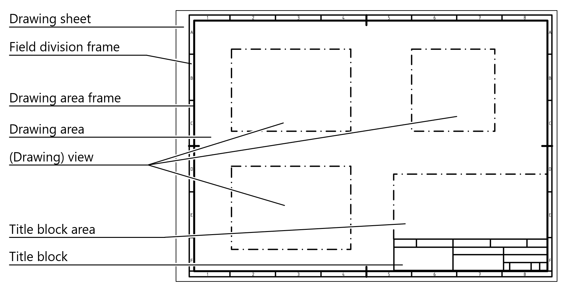
A Drawing sheet is a section of a →Technical drawing, which has the same parts number as other sections, but its own representation and storage. (see DIN EN ISO 7200:2004)
The following terms apply to the structure of drawing sheets:
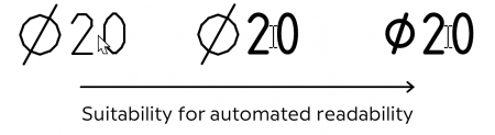
Various data formats have been established for the digital exchange of →technical drawings. Each data format transports at least the graphic information of a drawing printed on paper. In addition, vector formats and especially specially developed drawing data formats store information that facilitates automated readout by computer programs.
Basically, a technical drawing is constructed according to largely internationally defined standards from linear graphic elements as well as text elements. The reader derives the meaning from the arrangement of the elements in relation to each other. However, this kind of interpretation work can only be implemented by software to a very limited extent. For this reason, additional information is stored in drawing data formats, which indicates to a software that the elements belong together and what they mean.
The suitability of different data formats for automated interpretation can be generalized as follows:
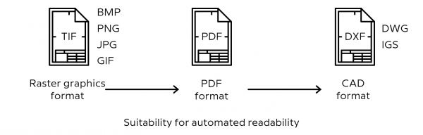
In infra CONVERT, a CAD exchange format is the minimum requirement for fully automatic feature recognition.
Raster graphic formats only transport the graphic information addressed to the reader. Software can only retrieve the stored information (“pattern recognition”) by relating the pixels to one another. Actually used technologies concentrate on text recognition, the so-called “Optical Character Recognition” (OCR). They have a recognition rate of about 50 to 70 %, at least in the area of technical drawings.
In infra CONVERT, drawings in raster graphic format can be stamped manually using the quick input dialog.
See
Functions > Characteristics > Manually stamp
Vector graphic formats, on the other hand, store graphic elements as unique, mathematically described graphic primitives. The latter mean basic geometric elements such as straight lines, arcs, and splines, as well as surfaces such as circles, polygons, and spline surfaces. Texts are stored either as polylines or with the help of character encoding (see also →Font).
In infra CONVERT, character-coded texts or embedded fonts are a prerequisite for automatic feature recognition.
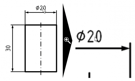
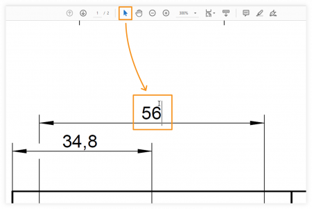
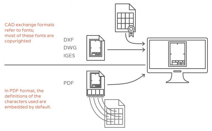
The PDF format (PDF = “Portable Document Format”) supports raster-based and vector-based data storage. Coded text characters are stored in text fields, such as “⌀ 20” in the adjacent example.
In infra CONVERT, drawings in raster-based PDF format can be stamped manually using the quick input dialog. PDF drawing files can be stamped automatically*, if the characters are encoded.
* A pro license is required.
See
Functions > Characteristics > Manually stamp
Functions > Characteristics > Automatic stamping
With the PDF format it should be noted that not all CAD systems export all characters encoded - usually special characters -, but as geometric elements. The suitability for automated readability is reduced accordingly.
You can test whether a PDF contains coded text with a PDF reader. For example, open the PDF with Adobe Acrobat Reader, activate the selection tool, and move the pointer to a text. If the cursor changes to an ![]() and you can select the text, it is coded text.
and you can select the text, it is coded text.
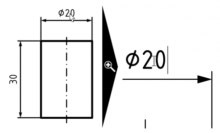
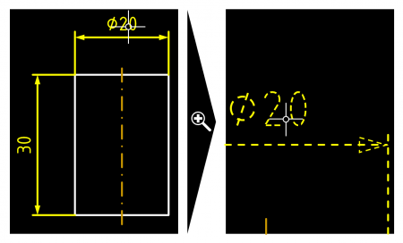
CAD formats store data largely based on design elements. Views, hatches, dimension entries etc. remain recognizable as such for a processing software, such as the dimension entry for the diameter 20 of the cylinder in the adjacent example.
In infra CONVERT drawings can be processed in DXF format (“Drawing Interchange File Format”, worldwide and neutral industry standard), in DWG format (Autodesk's own format, also supported by most CAD systems) or in IGES format* (“Initial Graphics Exchange Specification”).
* A license for the IGES module is required.
Note The multicolored representation of native CAD drawing formats has the background that the colors encode line widths. In the early days of CAD, different line widths could only be displayed poorly on the screen using the technology of the time. An ink pen was assigned to a color on the plotter. An assignment table for line widths (“pentable”) is usually not exported to the usual exchange formats. For better legibility, infra CONVERT therefore displays drawings in monochrome (“black on white”) as standard.
Non-graphic information is specified in technical drawings using characters. Characters can be letters, numbers, diacritics, punctuation marks, and additional graphic symbols. Due to their frequent repetition, they are grouped into a stock, the character set. In electronic data processing, characters are uniquely identified by coding in a character set. Numerous standards exist worldwide for character coding. “ASCII” is an example of a very small set, “Unicode” an example of a very large set to which characters are continuously added. A digital character set is called a font. A font file usually contains a character set with a uniform graphic design.
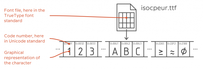
In addition to the purely visual representation of characters, the unambiguous definition of characters is important for the automatic analysis of technical drawings. PDF files are generally used to displaying characters correctly. This is because the character definitions used are saved (embedded) in the file. This is (unfortunately) different with the CAD exchange formats DXF, DWG and IGES. In them only the references to characters are stored in font files. The font files are therefore required for correct display.
Significance for infra CONVERT Fonts are protected by copyright. In most cases, the rights of use are only granted for a fee. The number of fonts used by CAD systems is immensely high. Supplying these fonts would disproportionately increase the cost of infra CONVERT licenses. For this reason, infra CONVERT replaces fonts not installed on the computer with visually similar fonts when loading drawing files. If this is the case, a note message is issued.
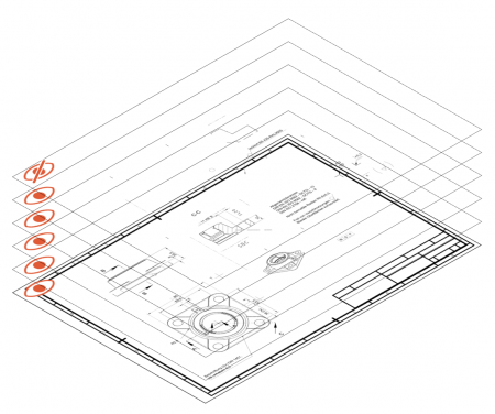 A Layer (also: “foil”) is a structuring aid in drawings and combines objects or drawing elements. Layers are placed on top of each other like transparent slides on an overhead projector, so that the content combined in this way shows the overall result. Layers have, among others, the properties show/hide (enabled/disabled), printable/not printable. If contents of a layer are not needed at a certain time, it can be hidden. Several drawing variants can be saved in one document or file, for example texts in several languages.
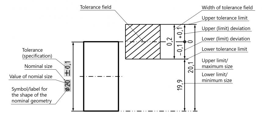
(Size-) measurements are used to specify geometric and other physical properties of a product (→variable characteristic). They are expressed as the multiple or part (numerical value) of a reference value (unit of measurement):
Size = Numerical value × Unit of measurement
The following graphic explains some of the terms used in infra CONVERT for linear measurements and measurement tolerances.
In infra CONVERT, the unit of measurement is assigned to a characteristic using the characteristic class. The following units with attachments for decimal parts and multiples from different unit systems are available.
Note Your CAQ system provider or administrator can change class names and associated units of measurement for you, see Administrator's Manual infra CONVERT 2019 > Configuration and Import > Parameter File “CharacteristicClasses”.
Note Your CAQ system provider or administrator can change class names and associated units of measurement for you, see Administrator's Manual infra CONVERT > Configuration and Import > Parameter file "CharacteristicClasses".
| Size type | Unit name | Unit- symbol | Reference | ID |
|---|---|---|---|---|
| Length, distance | Micrometer | µm | DIN 1301-1:2010-10 | Micrometer |
| Millimetre | mm | DIN 1301-1:2010-10 | Millimeter | |
| Centimetre | cm | DIN 1301-1:2010-10 | Centimeter | |
| Decimetre*¹ | dm | DIN 1301-1:2010-10 | Decimeter | |
| Metre | m | DIN 1301-1:2010-10 | Meter | |
| Mikroinch | µin | [NIST-19] | Microinch | |
| Milliinch | mil | [NIST-19] | Mil | |
| Inch | in | [NIST-19] | Inch | |
| Foot | ft | [NIST-19] | Foot | |
| Yard | yd | [NIST-19] | Yard | |
| Angle | Degree | ° | DIN 1301-1:2010-10 | Degree |
| Radiant*² | rad | DIN 1301-1:2010-10 | Radiant | |
| Steradiant*² | sr | DIN 1301-1:2010-10 | Steradiant | |
| Area | Square millimetre*³ | mm² | DIN 1301-1:2010-10 | SqareMillimeter |
| Square centimetre*³ | cm² | DIN 1301-1:2010-10 | SquareCentimeter | |
| Square metre*³ | m² | DIN 1301-1:2010-10 | SquareMeter | |
| Volume | Kubikmillimetre*¹ | mm³ | DIN 1301-1:2010-10 | CubicMillimeter |
| Cubic millimetre*¹ | cm³ | DIN 1301-1:2010-10 | CubicCentimeter | |
| Cubic centimetre*¹ | dm³ | DIN 1301-1:2010-10 | CubicDecimeter | |
| Cubic metre*¹ | m³ | DIN 1301-1:2010-10 | CubicMeter | |
| Milliliter*³ | ml | DIN 1301-1:2010-10 | Milliliter | |
| Liter, Litre*¹ | l, L | DIN 1301-1:2010-10 | Liter | |
| Cubic inch*² | in³ | [NIST-19] | CubicInch | |
| Mass, weight | Microgram*¹ | µg | DIN 1301-1:2010-10 | Microgram |
| Milligram*¹ | mg | DIN 1301-1:2010-10 | Milligram | |
| Gram | g | DIN 1301-1:2010-10 | Gram | |
| Kilogram | kg | DIN 1301-1:2010-10 | Kilogram | |
| Ton | t | DIN 1301-1:2010-10 | Ton | |
| Gran/Grain | gr | [NIST-19] | Grain | |
| Dram | dr | [NIST-19] | Dram | |
| Ounce | oz | [NIST-19] | Ounze | |
| Pound | lb | [NIST-19] | Pound | |
| Pound-mass*² | lb | – | PoundMass | |
| Tex*² | tex = 1 g/km | DIN 1301-1:2010-10 | Tex | |
| Milligrams per square metre*³ | mg/m² | – | MilligramPerSquareMeter | |
| Force | Newton*¹ | N | DIN 1301-1:2010-10 | Newton |
| Decanewton*¹ | daN | DIN 1301-1:2010-10 | DecaNewton | |
| Kilonewton*¹ | kN | DIN 1301-1:2010-10 | KiloNewton | |
| Newton per metre*¹ | N/m | – | NewtonPerMeter | |
| Pound-force*² | lbf | – | PoundForce | |
| Pressure | Millibar*¹ | mbar | DIN 1301-1:2010-10 | Millibar |
| Bar*¹ | bar | DIN 1301-1:2010-10 | Bar | |
| Pascal*¹ | Pa | DIN 1301-1:2010-10 | Pascal | |
| Hectopascal*¹ | hPa | DIN 1301-1:2010-10 | Hectopascal | |
| Kilopascal*¹ | kPa | DIN 1301-1:2010-10 | Kilopascal | |
| Megapascal*¹ | MPa | DIN 1301-1:2010-10 | Megapascal | |
| Pound-force per square inch*² | lbf/in² | [NIST-19] | PoundForceSquareInch | |
| Zeit | Millisecond*¹ | ms | DIN 1301-1:2010-10 | Millisecond |
| Second*¹ | s | DIN 1301-1:2010-10 | Second | |
| Minute*¹ | min | DIN 1301-1:2010-10 | Minute | |
| Hour*¹ | h | DIN 1301-1:2010-10 | Hour | |
| Per millisecond*¹ | 1/ms | DIN 1301-1:2010-10 | PerMillisecond | |
| Per second*¹ | 1/s | DIN 1301-1:2010-10 | PerSecond | |
| Per minute*¹ | 1/min | DIN 1301-1:2010-10 | PerMinute | |
| Per hour*¹ | 1/h | DIN 1301-1:2010-10 | PerHour | |
| Speed | Metre per second | m/s | DIN 1301-1:2010-10 | MeterPerSecond |
| Metre per minute | m/min | DIN 1301-1:2010-10 | MeterPerMinute | |
| Kilometres per hour | km/h | DIN 1301-1:2010-10 | KilometerPerHour | |
| Flow rate | Liters per minute*³ | l/min | DIN 1301-1:2010-10 | LiterPerMinute |
| Cubic metres per second*³ | m³/s | – | CubicMeterPerSecond | |
| Cubic metres per minute*³ | m³/mih | – | CubicMeterPerMinute | |
| Mass flow | Kilograms per second*³ | l/min | DIN 1301-1:2010-10 | KilogramPerSecond |
| Energy, work, heat | Newtonmillimetre*⁴ | Nmm | - | Newtonmillimeter |
| Newtonmetre | Nm | DIN 1301-1:2010-10 | Newtonmeter | |
| Joule*³ | J | DIN 1301-1:2010-10 | Joule | |
| Pound-force-inch*² | lbf-i | – | PoundForceInch | |
| Pound-force-foot*² | lbf-ft | – | PoundForceFoot | |
| Effort | Milliwatt*³ | mW | DIN 1301-1:2010-10 | Milliwatt |
| Watt*³ | W | DIN 1301-1:2010-10 | Watt | |
| Kilowatt*³ | kW | DIN 1301-1:2010-10 | Kilowatt | |
| Temperature | Degrees Celsius | °C | DIN 1301-1:2010-10 | Celsius |
| Degrees Fahrenheit | °F | [NIST-19] | Fahrenheit | |
| Kelvin*¹ | K | DIN 1301-1:2010-10 | Kelvin | |
| Electricity | Volt*³ | V | DIN 1301-1:2010-10 | Volt |
| Ampere*³ | A | DIN 1301-1:2010-10 | Ampere | |
| Nanoampere*⁶ | nA | DIN 1301-1:2010-10 | NanoAmpere | |
| Microampere*⁶ | µA | DIN 1301-1:2010-10 | MicroAmpere | |
| Milliampere*⁶ | mA | DIN 1301-1:2010-10 | MilliAmpere | |
| Kiloampere*⁶ | kA | DIN 1301-1:2010-10 | KiloAmpere | |
| Megaampere*⁶ | MA | DIN 1301-1:2010-10 | MegaAmpere | |
| Gigaampere*⁶ | GA | DIN 1301-1:2010-10 | GigaAmpere | |
| Ohm*³ | Ω | DIN 1301-1:2010-10 | Ohm | |
| Nanoohm*⁶ | nΩ | DIN 1301-1:2010-10 | NanoOhm | |
| Microohm*⁶ | µΩ | DIN 1301-1:2010-10 | MicroOhm | |
| Milliohm*⁶ | mΩ | DIN 1301-1:2010-10 | MilliOhm | |
| Kiloohm*⁶ | kΩ | DIN 1301-1:2010-10 | KiloOhm | |
| Megaohm*⁶ | MΩ | DIN 1301-1:2010-10 | MegaOhm | |
| Gigaohm*⁶ | GΩ | DIN 1301-1:2010-10 | GigaOhm | |
| Ampere per centimeter*⁴ | A/cm | – | AmperePerCentimeter | |
| Ampere per meter*⁴ | A/m | – | AmperePerMeter | |
| Millitesla*⁴ | mT | – | MilliTesla | |
| Tesla*⁴ | T | - | Tesla | |
| Volt*³ | V | DIN 1301-1:2010-10 | Volt | |
| Nanovolt*⁶ | nV | DIN 1301-1:2010-10 | NanoVolt | |
| Microvolt*⁶ | µV | DIN 1301-1:2010-10 | MicroVolt | |
| Millivolt*⁶ | mV | DIN 1301-1:2010-10 | MilliVolt | |
| Kilovolt*⁶ | kV | DIN 1301-1:2010-10 | KiloVolt | |
| Megavolt*⁶ | MV | DIN 1301-1:2010-10 | MegaVolt | |
| Gigavolt*⁶ | GV | DIN 1301-1:2010-10 | GigaVolt | |
| Sound | Phon*⁵ | phon | – | Phon |
| Sone*⁵ | sone | – | Sone | |
| Level | Decibel*³ | dB | DIN 5493:2013-10 | Decibel |
| Auxiliary units | Number (of pieces)*³ | pcs = Stk. | – | Piece |
| Per million, Parts per million*¹ | pm = ppm | – | PerMillion | |
| Percent*¹ | % | DIN 5466:1983-02 | Percent | |
| Mol*³ | mol | DIN 1301-1:2010-10 | Mol | |
| NIST-19: National Institute of Standards and Technology, Gaithersburg, Maryland, USA: NIST Handbook 44 : Specifications, Tolerances, and Other Technical Requirements for Weighing and Measuring Devices (Appendix C. General Tables of Units of Measurement) 2019. *¹ Available from program version 1.2.0.23 *² Available from program version 1.3.9.5 *³ Available from program version 1.3.9.8 *⁴ Available from program version 2.1.1 *⁵ Available from program version 2.10.0 *⁶ Available from program version 4.2.0 |
||||
The numerical precision is relevant for the representation of numerical values. If a technical fact is described with numerical values, usually in the form of physical quantities or →measurement sizes, the accuracy of the displayed number should be in the same order of magnitude as the inaccuracy of the measure itself.
For example, the maximum inaccuracy range of the value 23, if no further information is available, is 22.5 to <23.5. Finally, the value may have resulted from a rounding operation. The last significant digit, here the “3”, is the digit that was rounded or may have been rounded.
| Value | Number of relevant digits | Rounding range (absolute inaccuracy range) | Size of the absolute inaccuracy range | Size of relative inaccuracy |
|---|---|---|---|---|
| 23 | 2 | 22,5 to <23,5 | 1 | 4,35 % |
| 2,3 | 2 | 2,25 to <2,35 | 0,1 | 4,35 % |
| 23,0 | 3 | 22,95 to <23,05 | 0,1 | 0,435 % |
| 2300 | 2 | 2250 to <2350 | 100 | 4,35 % |
| 0,000230 | 3 | 0,0002295 to <0,0002305 | 0,000001 | 0,435 % |
The number of significant or relevant digits in a decimal number can be identified as follows (see also “DIN EN ISO 80000-1:2013-08, Chapter 7.3.4 Deviation and uncertainty”):
The numerical accuracy common in technology (“slide rule accuracy”) is achieved by rounding a value so that three significant digits remain. Unless the first significant digit is a one, four significant digits should remain.
Testing tasks are planned in infra CONVERT and are project based. A project contains the test plan versions, →Drawing sheets as well as project-related settings. This data is stored together in an ICPX file.
A project supports the versioning of →Test plans. Characteristics already identified and settings already made can be transferred from one test plan version into the next within a project.

Even if it is technically possible, a project should always only refer to an object that is subject to a test and, if necessary, follow-up tests. This may be, for example, the initial sampling of a product and its subsequent re-sampling (first-piece approvals, requalifications).
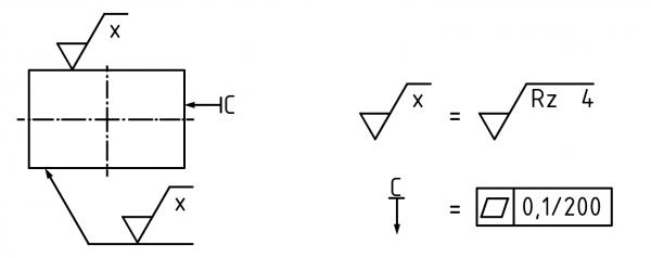
By using a simplified specification, requirements for a geometry element are specified in simplified form and explained elsewhere in the drawing, for example next to a view or near the title block. This type of specification can be useful if there is not enough space available in a view or if a specification applies to several separate geometry elements and is specified more than once.
The following example shows the principle for surface specifications and geometric tolerance specifications.
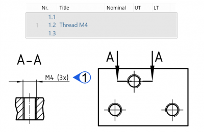
→Characteristics are derived from drawing entries. If a drawing entry collectively specifies several similar geometric elements of a component and each of these geometric elements is to be checked individually, further individual characteristics are derived from the original characteristic. In infra CONVERT three possibilities are available for this.
Multiple characteristic
A multiple characteristic is linked to the drawing entry via a stamp containing the basic number (“1”). Depending on its property “number of repetitions”, a corresponding number of individual characteristics are provided in the test plan (“1.1”, “1.2”, “1.3”) and exported. However, the properties can only be edited comprehensively for the multiple characteristic.
See User interface > Function windows > Characteristic properties> Properties
See Settings > Settings > Characteristics > “Dimensions with details of repetitions” group
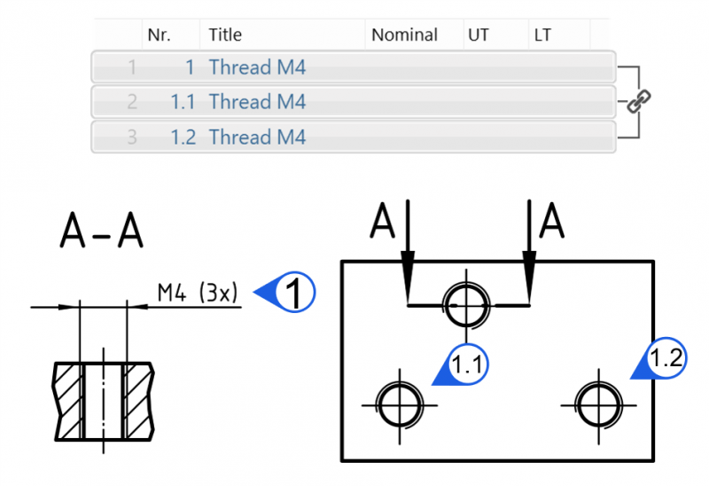
Duplicated Characteristic
The Duplicate function creates a copy of a characteristic with its own stamp. The characteristic properties can be edited independently. However, the copies remain linked to each other by the stamp number.
See Functions > Characteristics > Duplicate and re-stamp
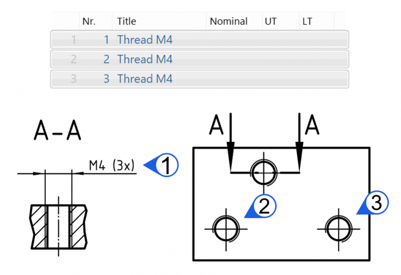
Erneut gestempeltes Merkmal
The Re-stamp function creates a copy of a characteristic with its own stamp. The copies are not linked together. The characteristic properties, including the stamp number, can be edited independently.
See Functions > Characteristics > Duplicate and re-stamp
The ISO GPS standard system based on DIN EN ISO 8015 regulates the language with which requirements for the geometry of a product are communicated. With an entry – constructed from “specification elements” – on the technical drawing, a specification operator in the standards system is invoked. A specification operator collates rules (“operations”) that are used to allow all the contract parties to understand the requirements of a geometric element or the relationship between geometric elements.
The principle of standard setting applies here, namely the “default principle”. Unless indicated through the addition of supplementary information in the contract agreement, the specification operator only includes default operations in a fixed order according to ISO standards. The default is chosen so that the operations approximately correspond to the most commonly used procedure and conventional understanding in practice.
In the following image, the concept is illustrated using the shaft geometric element with a nominal diameter of 20 mm as an example. At first only the defaults specification is considered, as shown on the left side. The drawing entry specifies a “linear size element” according to DIN EN ISO 14405-1 of the type “cylinder”. The default specification operator demands consideration of the “local two-point size”: All independently determined individual distances from opposite lying points must lie within the tolerance range, i.e. according to tolerance code “h9” of DIN EN ISO 286-1 at an interval of between 19.948 mm and 20 mm. Five arbitrary two-point sizes on the non-ideal surface model are represented as a geometric equivalent.* One suitable means of verification (“verification operator”) for this specification would be to carry out a check using a go/no go gauge: 1) Pass check (go): Is the maximum material size exceeded?; 2) Fail check (no-go): Is the minimum material size undershot?
* The operations of the specification operator in detail: The extracted lateral surface is assigned an ideal cylinder using the least squares method (Gaussian). The extracted lateral surface is to be cut at each height perpendicular to the derived centreline of this associated cylinder. At each cutting plane, the surface line is assigned an ideal circle according to the Gaussian method. A horizontal line is generated through each point on the surface line and the circle midpoint. If there is exactly one second intersection point with the surface line with respect to the midpoint, the distance between the two surface line intersection points is the two-point size to be matched with the interval.
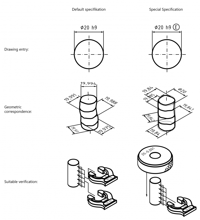
The deviation from the default setting can be identified using suitable specification modifiers (and/or abbreviations). In this way a “special specification operator” is obtained. In this example, the “E in circle” modifier symbol sets the envelope condition. The envelope condition requires that the evaluated geometry lies in an enveloping cylinder 20 mm in diameter and that all two-point sizes are greater than or equal to 19.948 mm. A suitable verification would be to test using a ring gauge or to carry out a no-go test using a go/no go gauge.
Below are examples of modifier text symbols with their meanings, such as those that can be assigned to a characteristic as property “modifiers” in infra CONVERT.
| Modifiers for linear sizes (according to DIN EN ISO 14405-1:2017-07; Characteristic classes: Length, diameter, spherical diameter) | |
|---|---|
| LP | Two-point size |
| LS | Local spherical size |
| LL | Local outer minimum material size |
| GG | Gauss method association criterion |
| GX | Maximum inscribed geometric element association criterion |
| GN | Minimum circumscribed geometric element association criterion |
| GC | Minimax association criterion |
| CC | Circumference diameter (calculated size) |
| CA | Area diameter (calculated size) |
| CV | Volume diameter (calculated size) |
| SX | Maximum rank-ordered size |
| SN | Minimum rank-ordered size |
| SA | Average rank-ordered size |
| SM | Median rank-ordered size |
| SD | Mid-range rank-ordered size |
| SR | Range of rank-ordered sizes |
| SQ | Standard deviation of sizes |
| E | Envelope requirement |
| /Length | Any limited part of the geometric element |
| ACS | Any cross-section |
| SCS | Specific fixed cross-section |
| ALS | Any longitudinal section |
| Number x | More than one geometric element Assigned as the number of repetitions of the characteristic as a property. |
| CT | Common tolerance |
| F | Condition of the free state |
| Modifiers for angular sizes (according to DIN EN ISO 14405-3:2017-07; Characteristic class: Angle) | |
|---|---|
| LC | Two-line angular size with minimax association criterion |
| LG | Two-line angular size with least squares association criterion |
| GG | Global angular size with least squares association criterion |
| GC | Global angular size with minimax association criterion |
| SX | Maximum angular size |
| SN | Minimum angular size |
| SA | Average angular size |
| SM | Median angular size |
| SD | Mid-range angular size |
| SR | Range of angular sizes |
| SQ | Standard deviation of angular size |
| SCS | Specific fixed cross-section |
| CT | Common tolerated angular size element |
| F | Condition of the free state |
| Modifiers for geometric features (according to DIN EN ISO 1101:2017-09; Characteristic classes: Geometrical tolerancing (form, orientation, location and run-out)) | |
|---|---|
| CZ | Combined zone |
| SZ | Separate zones |
| UZ | Specified tolerance zone offset |
| OZ | Unspecified linear tolerance zone offset (offset zone) |
| VA | Unspecified angular tolerance zone offset (variable angle) |
| C | Minimax (Chebyshev) feature |
| G | Least squares (Gaussian) feature |
| N | Minimum circumscribed feature |
| T | Tangent feature |
| X | Maximum inscribed feature |
| A | Derived feature |
| P | Projected tolerance zone |
| C | Minimax (Chebyshev) feature without constraint |
| CE | Minimax (Chebyshev) feature with external material constraint |
| CI | Minimax (Chebyshev) feature with internal material constraint |
| G | Least squares (Gaussian) feature without constraint |
| GE | Least squares (Gaussian) feature with external material constraint |
| GI | Least squares (Gaussian) feature with internal material constraint |
| N | Minimum circumscribed feature |
| X | Maximum inscribed feature |
| T | Total range of deviations |
| P | Peak height |
| V | Valley depth |
| Q | Standard deviation |
| UF | United feature |
| LD | Minor diameter |
| MD | Major diameter |
| PD | Pitch diameter |
| ACS | Any cross section |
| M | Maximum material requirement |
| L | Least material requirement |
| R | Reciprocity requirement |
| F | Free state condition (non-rigid parts) |
| CF | Contacting feature |
| E | Envelope requirement |
Functions and properties of products are agreed and documented between customer and supplier in specifications, including →Technical drawings and Specification sheets. Test processes are then implemented to compare the functions and properties of the manufactured samples, prototypes, products etc. with the specifications and the results recorded in test reports. The connection between the required and tested characteristic must be able to be made absolutely clear in this instance. Specifications put together in lists (e.g. specification sheets) make referencing simpler due to the entries that are already in place. Graphical presentation formats, such as in technical drawings, generally do not contain any clear tagging of individual →Test characteristics, when they leave the design office. Adding identifiers to the respective characteristic has proven to be viable (see DIN 6550:2006).

A characteristic identifier consists of the graphic characteristic symbol and the, mostly numeric, characteristic number. A clear correlation to the test characteristic is established together with the part number of the technical drawing. Usually when the characteristic attribute is changed (due to a change in the drawing) the same characteristic number remains, the number is blocked on deletion and the next previously unused characteristic number is assigned once a characteristic is added.
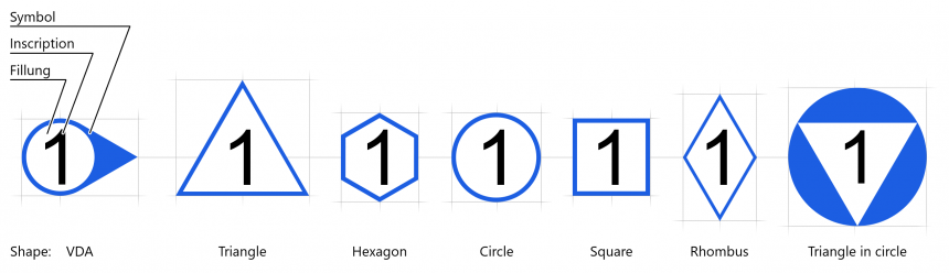
Characteristic identifiers were originally, and continue to remain to date, attached to paper drawings manually using a stamp tool and the requirements manually transferred in →Test plans. The process of attaching characteristic markings and transferring characteristic attributes into the test plan has been abbreviated to Stamping since then. The characteristic identifier is designated as Stamp in infra CONVERT. The stamp is formed from Stamp symbol and Stamp inscription (alphanumeric).
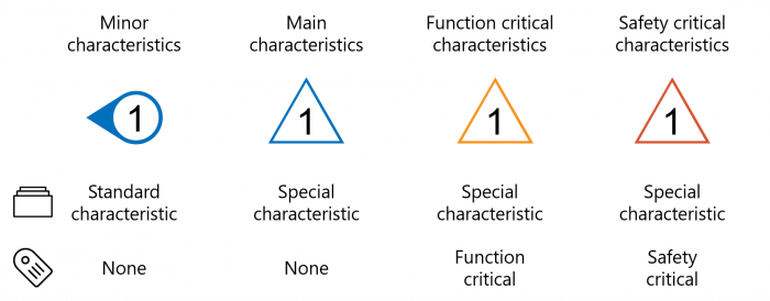
→Characteristic categories, for example, can be made visible in infra CONVERT by assigning them with one of the following six stamp symbol shapes as well as a symbol color.
→Test characteristics can also be assigned individual tags in infra CONVERT in addition to →Categories. While categories indicate a basic handling of test characteristics (relevance for testing, based on standard specifications), tags are intended to support the test process by increasing the clarity. Thus, tags may refer to measuring stations, measuring devices or test intensity for example.
Assigned tags are exported by infra CONVERT in the test plan, provided that they are supported by export format. Tagged test characteristics are identified on the drawing by coloration of the stamp.

Example Graduation of special characteristics
A test plan is a working instruction for a (quality) test. A major component in this respect is a compilation of the requirements on the object to be tested (or then process), e. g. in the form of a list of →Test characteristics.
The test plans of a project can be retrieved in infra CONVERT via the Project overview (see User interface > Function window > Project overview). The list of characteristics assigned to a test plan can then be viewed in the Characteristics overview function window (see User interface > Function window > Characteristics overview). The properties of each of the characteristics contained therein are displayed in the Characteristics properties function window (see User interface > Function window > Characteristics properties).

A test plan is exported from infra CONVERT, e.g. for further processing in a →CAQ system, in the form of an exchange format (JSONV1 or DFD, see Administrator Guide infra CONVERT > Export).
A test plan can contain the following information, for example:

The Tolerance table is the section of a norm that governs the general dimensional, shape and/or positional tolerance for workpieces. The limit values are assigned to nominal dimensional ranges within the table, whereby the limit values are further graded based on the Tolerance classes (also: Tolerance grades or Tolerance series), e.g. “fine, medium, coarse, very coarse” or “intrinsic, not intrinsic”.
General tolerances for length measurements, angle measurements and edge dimensions (curve radii and chamfers) can be automatically assigned to the nominal dimensions in infra CONVERT based on the loaded tolerance tables.
Legal note You do not acquire any user rights to the tolerance tables contained in the infra CONVERT software upon purchase. You yourself must obtain lawful access to the corresponding texts, such as the norms and other agreements. You have the option of creating tolerance tables yourself (see Administrator Guide infra CONVERT > Configuration and import > Tolerance tables) or have them created by us based on your data.