infra CONVERT
blue DAT • infra DAT
mdm TOOL
infra CONVERT
blue DAT • infra DAT
mdm TOOL
This is an old revision of the document!
A characteristic or several characteristics can be automatically →stamped with this function. It is necessary that the drawing file is formatted as a DWG, DXF or IGES, see →Drawing data format.
| Step | Action | Result | |
|---|---|---|---|
| 1 | Open drawing sheet | Open the drawing sheet that you would like to stamp. | The drawing sheet is displayed in the drawing window. |
| 2 | Activate stamp tool | Click on the Stamp tool button ( | If you now move the mouse pointer into the drawing window, it will be displayed as a stamp (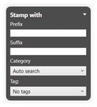 |
| 3 | Check/set start value for the numbering | 1) Set the start value in the Stamp-with dialog or in the Characteristic overview window. You can use the three-dot button in the Stamp number field to set the start value or the next free number via a context menu. | 1) The starting value is fixed. |
| 2) Define further properties in the Stamp with dialog: • Prefix and suffix as a supplement for the stamp text • Category • Tag • Tolerance table and class for generally tolerated dimensions | 2) The properties are fully selected. | ||
| 4 | Stamp | There are three alternative sub-functions available for the actual stamping: 4a) Stamp a characteristic individually. 4b) Automatically recognize and stamp all characteristics in one area. |
|
| 4a | Stamp individual characteristic | Move the mouse pointer (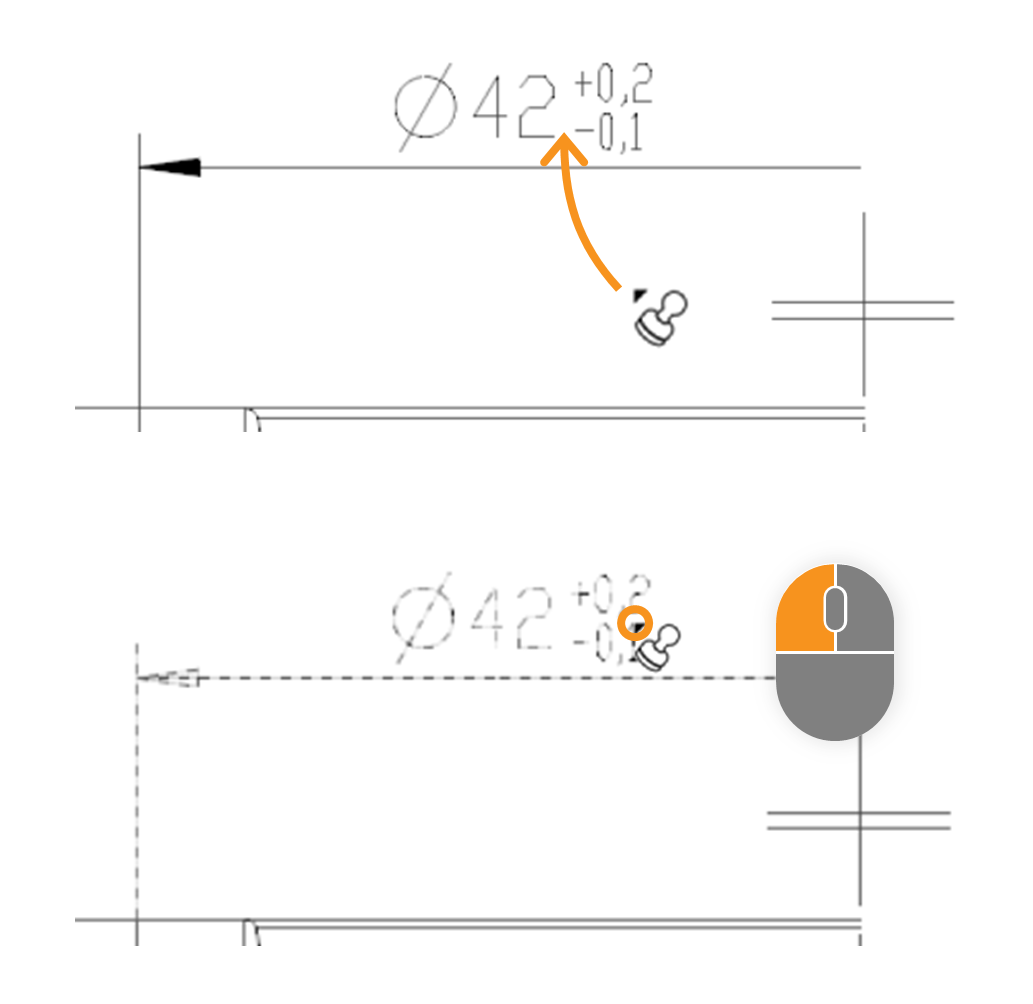 | In the expample the size “□86” is stamped. After stamping, it received a stamp with the number “1” and appears as an entry in the characteristic overview: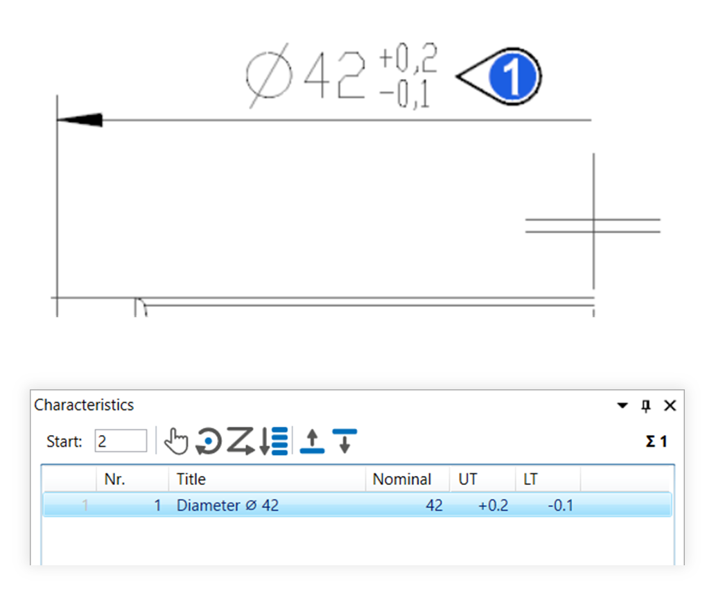 |
| 4b | Stamp area | Move the mouse pointer (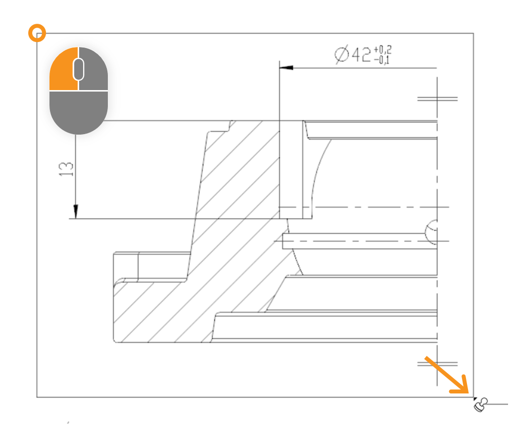 | After stamping, all relevant characteristics of the area received a VDA stamp with numbers from “1” to “7” and appear as an entry in the characteristics overview: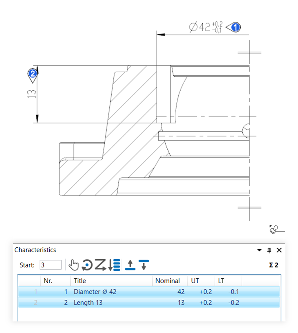 |
| Step | Action | Result | |
|---|---|---|---|
| 1 | Open drawing sheet | Open the drawing sheet that you would like to stamp. | The drawing sheet is displayed in the drawing window: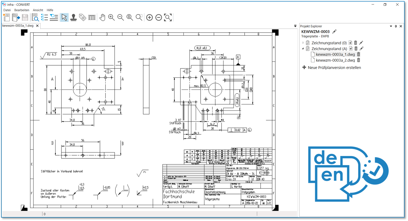 |
| 2 | Activate stamp tool | Click on the Stamp tool button in the Toolbar | If you now move the mouse pointer into the drawing window, it will be displayed as a stamp ( |
| 3 | Check/set start value for the numbering | The number is assigned to the first characteristic in the test plan during stamping that is stored in the settings (see Customization > Settings > Stamp) as a start value, usually 1. Each additional stamp receives a number incremented by the set increment. The counter will be at the lowest possible value if characteristics are already present in the test plan. Open the Characteristic overview to check or alter the counter reading, e.g. by clicking on the Open characteristic overview | The counter for the numbering in the example is set as required at 1: |
| 4 | Stamp | There are three alternative sub-functions available for the actual stamping: 4a) Stamp a characteristic individually. 4b) Automatically recognize and stamp all characteristics in one area. 4c) Stamp a drawing entry, which is not recognized as interrelated, as a characteristic. |
|
| 4a | Stamp individual characteristic | Move the mouse pointer ( | We decided on the length measurement of 80 in the front view in the example. After stamping, it received a VDA stamp with the number 1 and appears as an entry in the characteristic overview: |
| 4b | Stamp area | Move the mouse pointer (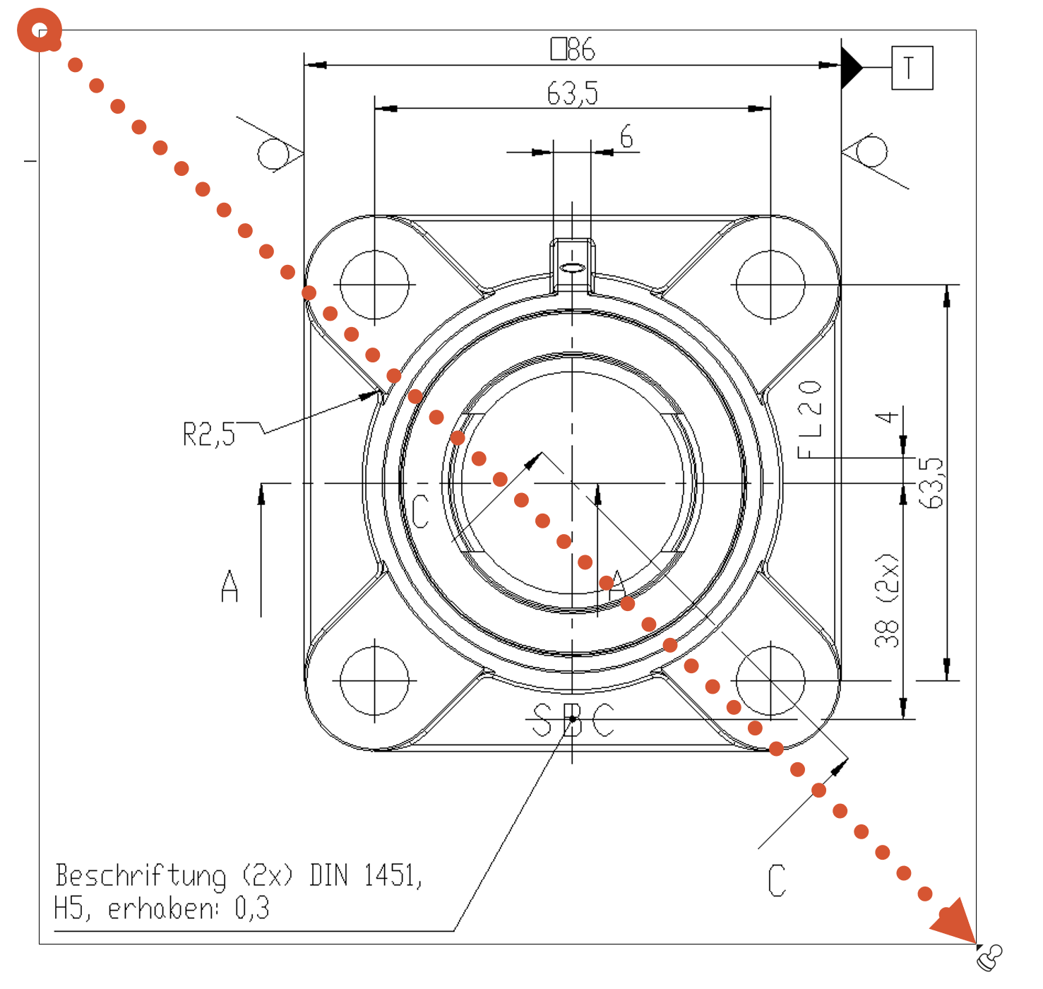 | After stamping, all relevant characteristics of the area received a VDA stamp with numbers from 1 to 13 and appear as an entry in the characteristics overview: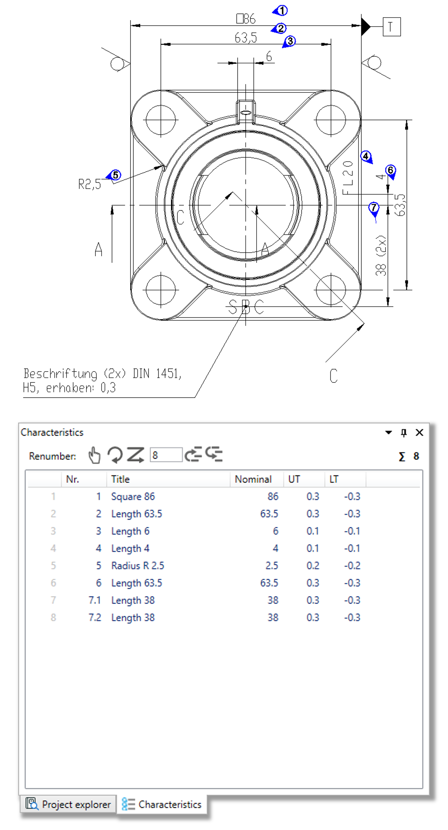 |
| 4c | Stamp group | 1) Move the mouse pointer (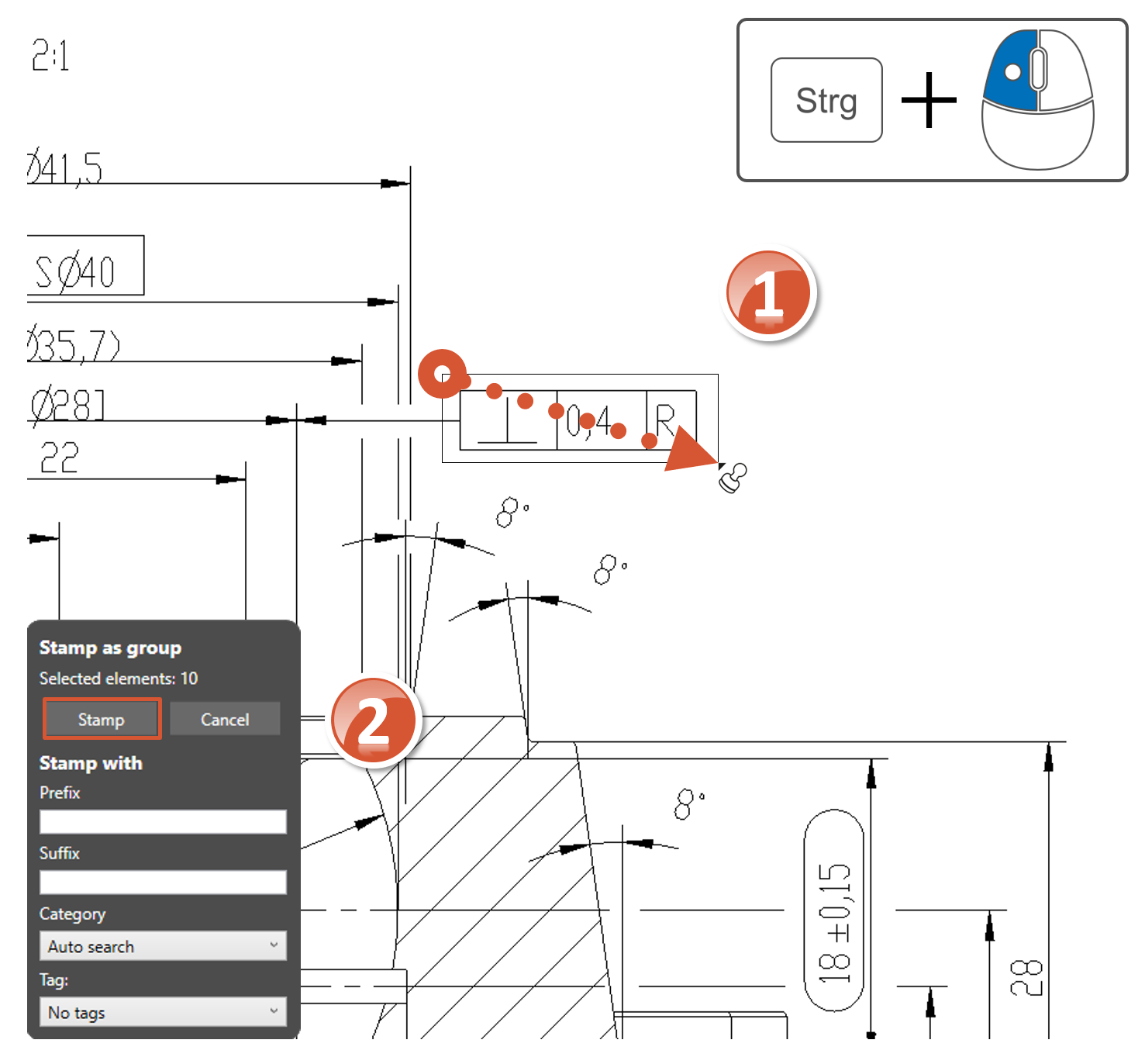 | 1) The number of detected elements are displayed in the Stamp as group dialog window for control purposes, it is ten in the example. These are the vector and text elements from which the drawing entry is built upon. |
| 2) Confirm the dialog by clicking on Stamp. | 2) The elements selected as a group have been recognized as a characteristic, stamped as such and taken over in the test plan: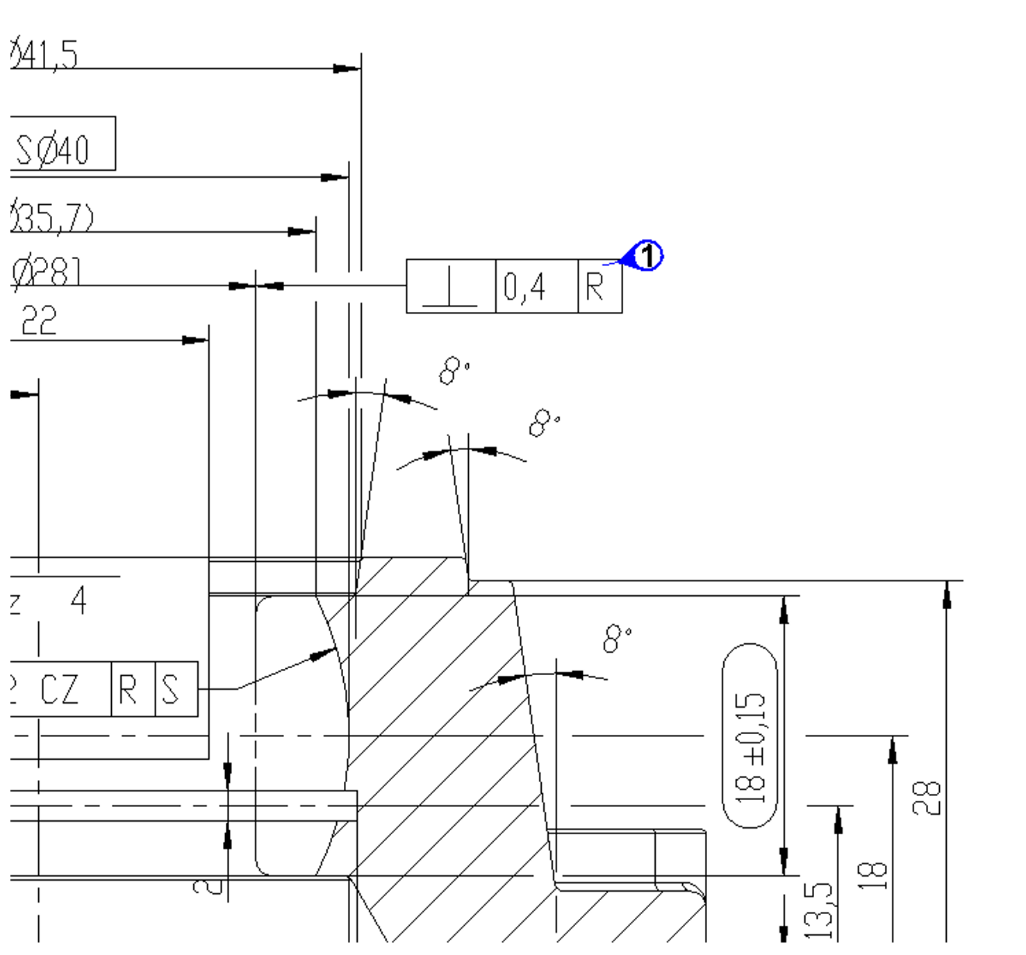 |
||
The function can be influenced via the following settings:
Creating characteristics
Change settings for creating characteristics.
See Settings > Settings > Characteristics
General tolerance tables
Change the underlying general tolerance tables, from which tolerance values for non-individually tolerated measurements are applied.
See Settings > Project settings > Tolerance tables
Stamp settings
Change underlying settings for stamp.
See Settings > Settings > Stamp
Stamp templates
Change the graphical display of the stamp.
See Settings > Project settings > Stamp templates