infra CONVERT
blue DAT • infra DAT
mdm TOOL
infra CONVERT
blue DAT • infra DAT
mdm TOOL
![]()
Quick start
With infra CONVERT, you can quickly and easily create high-quality test plans based on technical drawings. All help topics for the user are prepared in the user manual.
infra CONVERT can be flexibly adapted to the work processes and connected systems in the company. The administrator's manual covers in-depth topics for preparing the program for use.
The following is an example of a common way to configure infra CONVERT and deploy the defaults across the enterprise. However, the settings do not need to be distributed via configuration file (step 3) and projects do not need to be prepared as templates (step 4).

Install program
Install infra CONVERT on the designated workstation PCs (clients).
See Installation > System requirements
See Installation > Installation

Set up license
Install the license service, a utility, on a license server you specify. Start infra CONVERT on any client and connect to the license server: Select Server and enter the name of the host. Send the displayed registration key to your provider. You will then receive a license file, which you load on the client in infra CONVERT. The license data is sent to the license server and stored there.
See Installation > Set up a server license

Configure program
Define the behavior of infra CONVERT in the settings, for example the default project template folder, details of the characteristic recognition, the type of stamp number assignment or the directory for Excel test report templates. You open the settings menu via Edit (menu bar) > Settings.
See Settings > Settings
Note Some settings can only be set in administrator mode.
See Settings > Settings > Administration > Open
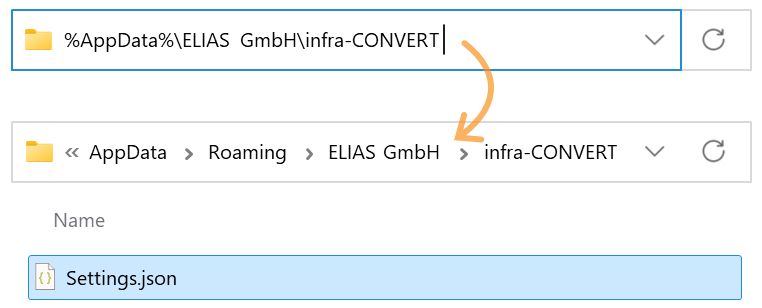
Your individual settings, if you have not worked in administrator mode, are stored in the configuration file Settings.json in the directory %AppData%\ELIAS GmbH\infra-CONVERT. Copy the file out here.
In administrator mode you can export all currently set settings directly: Edit > Settings > Administration.
See Settings > Settings > Administration > “Export configuration files” group
Open the Settings.json file with a text editor and delete all unnecessary settings, especially user-specific paths.
See Administrator's Manual > Configuration and import > “Settings” Parameter file > List of the settings
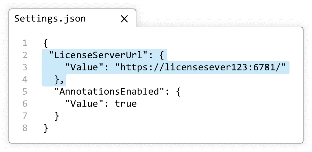
The two setting parameters in the adjacent example specify the path to the license server (LicenseServerUrl) and enable the annotation function (AnnotationsEnabled).
Setting parameters are written consecutively in the form ″Parameter″: { } and separated by a comma. The order does not matter.
You can now make the prepared configuration file available to other users on the workstation PCs, either in the ProgramData or in the user-specific AppData directory. We recommend the AppData directory.
| %ProgramData%\ELIAS GmbH\infra-convert | %AppData%\ELIAS GmbH\infra-CONVERT | |
|---|---|---|
| Advantages |  If several users are working on one computer, the configuration file only needs to be exchanged in one place. If several users are working on one computer, the configuration file only needs to be exchanged in one place. | Users can copy the configuration file to the directory by themselves. If user-specific settings already exist, these are reset with this. |
| Disadvantages |  The directory can only be written to with administrative rights. Any existing user-specific settings in the AppData directory are retained and take precedence. The directory can only be written to with administrative rights. Any existing user-specific settings in the AppData directory are retained and take precedence. | The configuration file must be copied to user directories. |

Create project templates
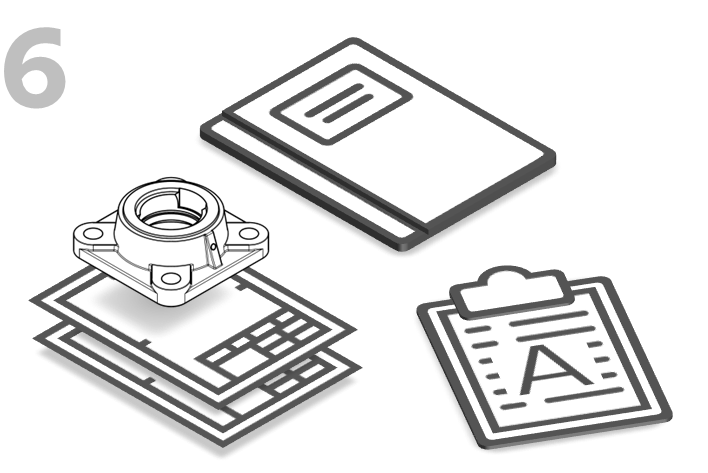
Name the project and the first test plan version. Define the tags, categories, and stamp templates.* Save the project as a template and store it on a file server, for example, so that it can be accessed centrally from all workstation PCs. Project templates can also be used, for example, to map different inspection planning scenarios.
See Functions > Projects > Save project as template
* – Class definitions can be customized with a text editor in the corresponding configuration file. After customization, a new project must be created to load the definitions.
See Administrator's Manual > Configuration and Import > Parameter file "CharacteristicClasses"

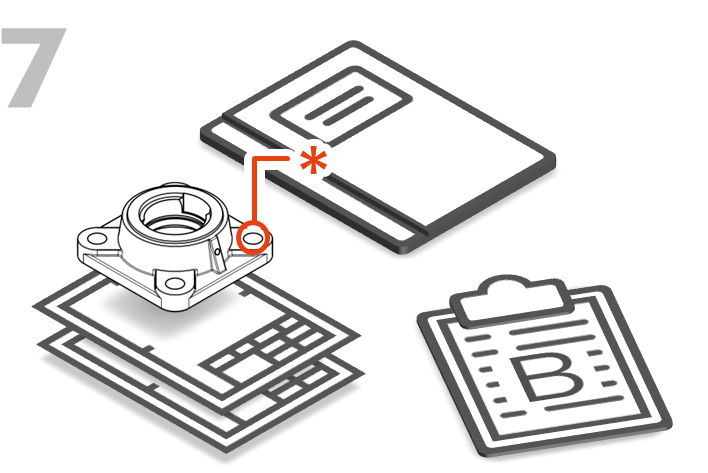
Create test report templates
Test plan data can be exported from infra CONVERT directly into an Excel test report. You can use or adapt the Excel templates supplied directly, but you can just as easily create your own templates or continue to use existing company templates.
See More > Create and customize Excel templates
The productive work can now be started.
Create project and test plan
Create a project for each object to be inspected (component or assembly with a part number). Several drawing sheets can be assigned to one test plan.
See From the drawing to the test plan
See Drawing data format
Versioning the test plan
In the event of a drawing change, you can use the drawing comparison to quickly and safely create a new test plan version based on the previous version. Test plan versions are managed within a project.
See Compare drawings
Below we will guide you through the basic steps to create a test plan from a drawing in infra CONVERT.


Alternatively, the free training videos (YouTube) are available.

(Full functional description: Functions > Projects > Create new project)
| Step | Action | Result | |
|---|---|---|---|
| 1 | Create project | There are three ways to create a new project: 1a) Create a blank project.¹ 1b) Create a blank project and load drawing sheets directly.¹ 1c) Create a project based on a template.² ¹ – The project configurations (definitions for classes, categories, tags, stamp templates) are loaded from individual configuration files. ² – Configuration files are disregarded, all project configurations are stored in the project template file (*.icpt). Available only in Pro version and from program version 3.2.0. |
|
| 1a | Create blank project | Click New Project ( | The “Project overview” window is displayed next to the drawing area. See User interface > Function window > Project overview Note 1 Only one project can be open and edited at a time. Note 2 The project is not saved yet. |
| 1b | Create project from drawing | 1) Click Create project from drawing ( Note Available from program version 3.0.0. | 1) The file manager of the operating system opens. |
| 2) You can now import one or more drawings. See Functions > Drawings > Import drawing | The “Project overview” window is displayed next to the drawing area. See User interface > Function window > Project overview Note 1 Only one project can be open and edited at a time. Note 2 The project is not saved yet. |
||
| 1c | Create project from template | Select a project template to create a project from it. Project templates provided in the template directory are listed on the Project Templates tab on the start page and under File (menu bar) > New from Template ( Project templates from another directory can be created on the start page via Create project from template ( A project can also be created by opening a project template file (*.icpt) directly from the file system. Note Available only in the Pro version and from program version 3.2.0. | A new project is created based on the project template. |
| 2 | Edit project title | 1) Next to the project title “New project” click the button | 1) The “Edit project” dialog box opens. |
| 2) Enter a unique name in the “Project title” field, under which you will later find the project again. The “Description” field can be used optionally. | 2) The information is entered. | ||
| 3 | Confirm information | Then click OK. | Project title and description have been taken over and are displayed accordingly. |

(Full functional description: Functions > Drawings > Import drawing)
| Step | Action | Result | |
|---|---|---|---|
| 1 | Invoke function | In the project overview, click on the Add drawing sheet button next to the (already created) test plan to which you want to assign the drawing | The file manager of your operating system opens. |
| 2 | Select the drawing sheets | Navigate to the storage location of the drawing sheets and load these (Double-click directory entry or select entry or mulitple entries and click on Open). Note IGES files can only be loaded with a license for the additional module “IGES”. | [A] Depending on the file format (*.dxf, *.dwg) and the default setting, the “Import drawing sheet” dialog opens, otherwise the drawing sheets are added directly as described under C):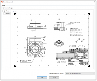 Note The function for selecting model and paper spaces is only available in the Pro version and from program version 1.4.0.5 onwards. |
[B] Depending on the file format (*.pdf) and the default setting, the “Import drawing sheet” dialog opens, otherwise the drawing sheets are added directly as described under C):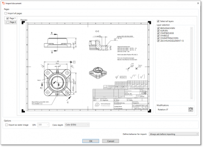 Note The option shown in the dialog is available as of program version 1.4.0.5. |
|||
C) The drawing sheets are displayed as entries in the “Project Overview” window: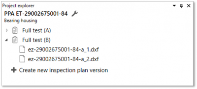 |
|||
| [3a] | [Optional] Selecting Sheets of a DXF or DWG | In the dialog “Import drawing sheet” you can select the desired sheets from the model space and the paper spaces. To do this, place a check mark on the tabs. By clicking on a tab you can preview the sheet. You can define the behavior for the following imports in the lower right corner of the dialog. | The drawing sheets are displayed as entries in the “Project Overview” window: |
| [3b] | [Optional] Select sheets of a PDF | In the dialog “Import drawing sheet” you can select the desired sheets of the PDF. To do this, place a check mark on the tabs. By clicking on a tab you can preview the sheet. In the right area “Layer selection” you can also select the desired layers. Under “Modifiers” you can turn the sheet by clicking on the button. You can define the behavior for the following imports in the lower right corner of the dialog. If you would like to convert the PDF into a raster graphic during import, you can set the check mark under “Options” at Import as Raster Graphic. You can also find the displayed setting options in the settings. Note The import of a PDF as a raster graphic is only available from program version 1.4.2.1. Note Turning pages is only possible from program version 1.5.1.1. | The drawing sheets are displayed as entries in the “Project Overview” window. |

(Full functional description: Functions > Characteristics > Automatic stamping; alternative function: Functions > Characteristics > Manually stamp)
| Step | Action | Result | |
|---|---|---|---|
| 1 | Open drawing sheet | Open the drawing sheet that you would like to stamp. | The drawing sheet is displayed in the drawing window. |
| 2 | Activate stamp tool | Click on the Stamp tool button ( | If you now move the mouse pointer into the drawing window, it will be displayed as a stamp (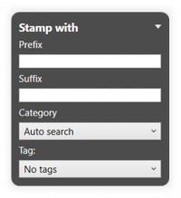 |
| 3 | Check/set start value for the numbering | 1) Set the start value in the Stamp-with dialog or in the Characteristic overview window. You can use the three-dot button in the Stamp number field to set the start value or the next free number via a context menu. | 1) The starting value is fixed. |
| 2) Define further properties in the Stamp with dialog: • Prefix and suffix as a supplement for the stamp text • Category • Tag • Tolerance table and class for generally tolerated dimensions | 2) The properties are fully selected. | ||
| 4 | Stamp | There are three alternative sub-functions available for the actual stamping: 4a) Stamp a characteristic individually. 4b) Automatically recognize and stamp all characteristics in one area. |
|
| 4a | Stamp individual characteristic | Move the mouse pointer (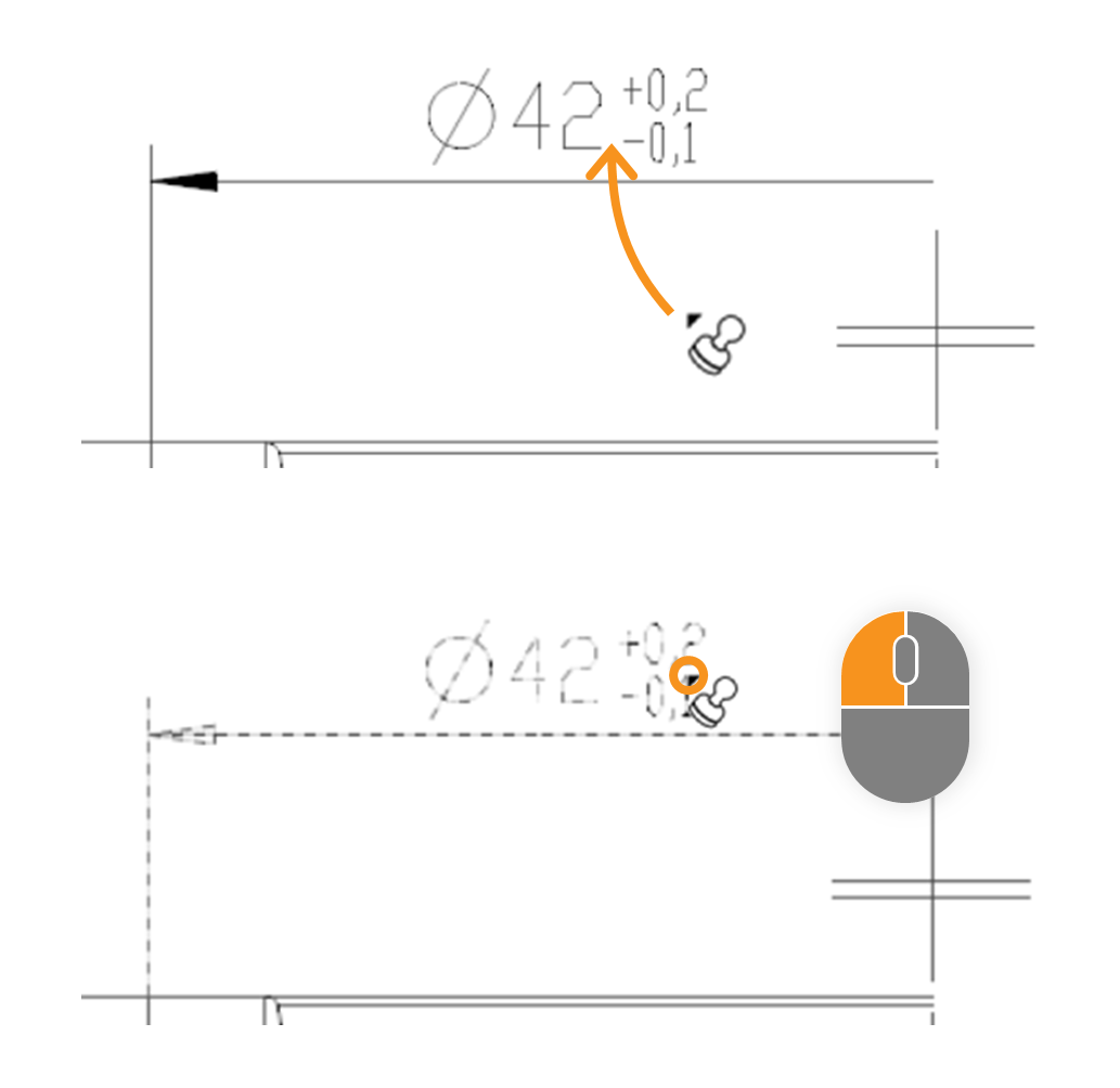 | In the expample the size “□86” is stamped. After stamping, it received a stamp with the number “1” and appears as an entry in the characteristic overview: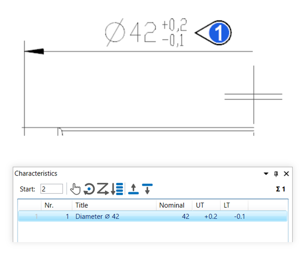 |
| 4b | Stamp area | Move the mouse pointer (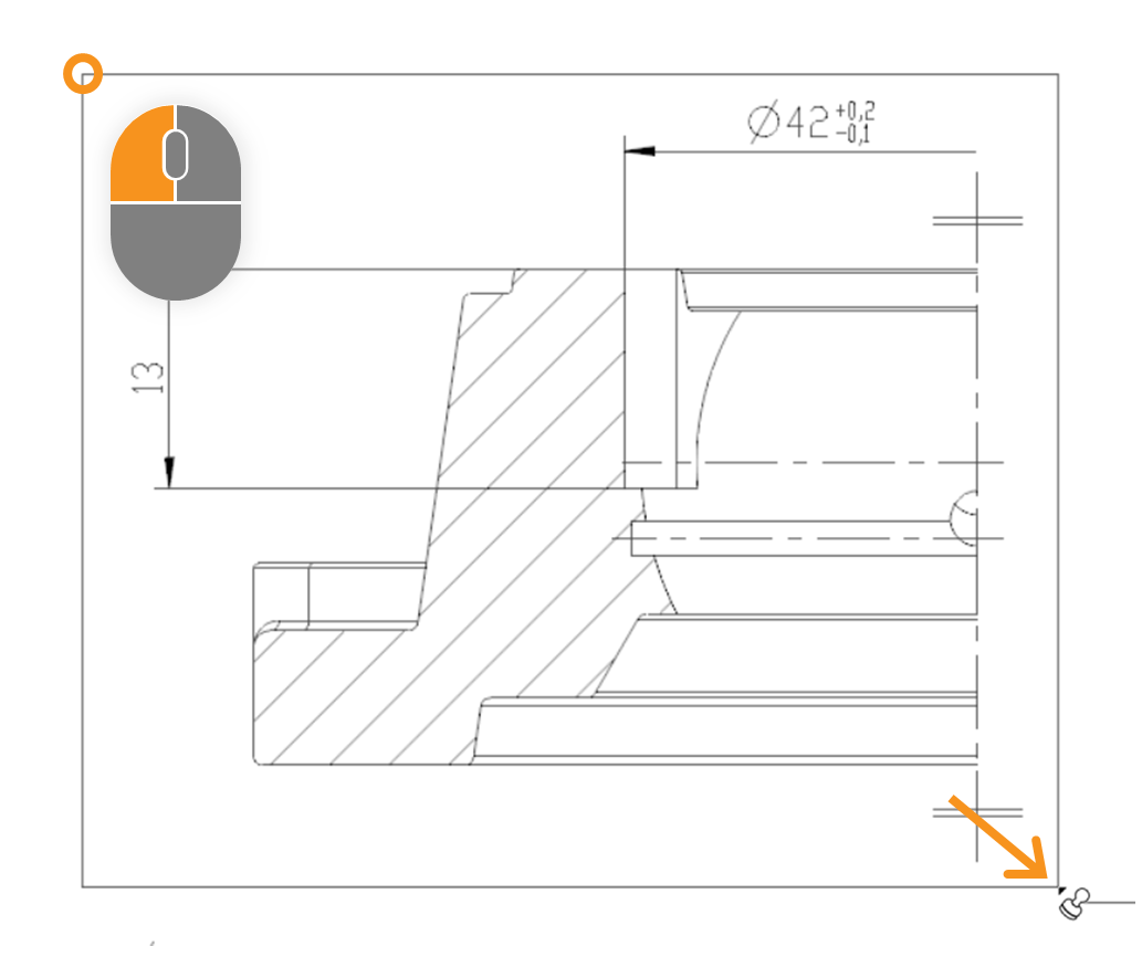 | After stamping, all relevant characteristics of the area received a VDA stamp with numbers from “1” to “7” and appear as an entry in the characteristics overview: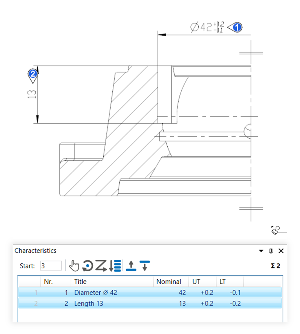 |

(Full functional description: Functions > Characteristics > Reposition and align stamp)
| Step | Action | Result | |
|---|---|---|---|
| 1 | Activate Selection tool | Click the Select Tool button ( Note You can also move stamps and targets with other tools. However, we recommend the Selection tool. |
|
| 2 | Move stamp or stamp targets | You can now: 2a) Move stamps 2b) Move stamp targets |
|
| 2a | Move stamps | 1) Click with the left mouse button on the stamp to be moved and keep the button pressed. To move several stamps together, first select them, right-click on one of the stamps and select Move stamp as group from the context menu. Note Move stamp as group is available from program version 4.2.9. | 1) The stamp (or group of stamps) is now coupled with the mouse pointer.  |
| 2) Release the stamp (or group of stamps) at the desired position. | 2) The stamp (or group of stamps) is now positioned and aligned. | ||
Additional function Press the STRG key while moving to snap the stamp to a grid. Note Available from program version 4.2.9. |
|||
| 2b | Move stamp targets | 1) Right-click the stamp whose destination you want to move and select Move stamp target ( To move the targets of multiple stamps together, first select the stamps, right-click on one of the stamps and choose Move stamp targets as group from the context menu. Note The context menu entry Move stamp target as well as moving stamp targets as a group is available from program version 4.2.9. | 1) The target point (or group of target points) is now linked to the mouse pointer.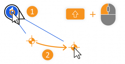 |
| 2) If you have started the function via the context menu, click the left mouse button at the desired position. If you are working with the Shift key, release the mouse button at the desired position. | 2) The target point (or group of target points) is now repositioned. | ||
Additional function Press the STRG key while moving to snap the stamp target to a grid. Note Available from program version 4.2.9. |
|||

(Full functional description: Functions > Characteristics > Change numbering)
| Step | Action | Result | |
|---|---|---|---|
| 2 | Set start value | Enter the desired number in the field for the start value in the Characteristics list function window, which is to be assigned for the next characteristic to be numbered. | The starting value is predetermined, for example “1”: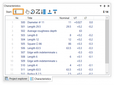 |
| 2 | Numbering | Four alternative functions are available for the numbering: 2a) Manually number 2b) Number clockwise 2c) Number in reading direction 2d) Renumber by list position |
|
| 2a | Manually number | 1) Click on the Manually number button ( | 1) The Manually number mode is now active. |
2) Move the mouse pointer over the drawing surface and click on the stamp of the desired characteristic.: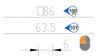 | 2) The characteristic number has been changed: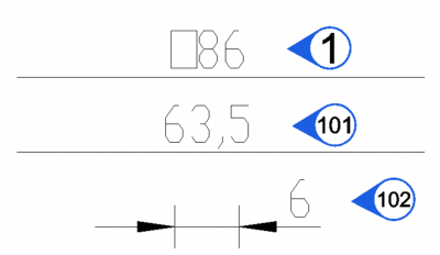 The next free number is now displayed in the field for the start number. Note If a number has already been assigned, the next free number is automatically selected. |
||
| 3) You can now click on additional characteristics or leave the Manually number mode by clicking on the Selection tool button ( | 3) If necessary, additional characteristics are re-numbered. The Manually number mode is now no longer active. | ||
| 2b | Number clockwise | 1) Select the characteristics to be numbered, either by selection in the characteristics list or on the drawing sheet (see also User interface > Operation – Special features when selecting). | 1) The desired characteristics are selected. The drawing view mentioned in step 1 is to be re-numbered consecutively in the example. |
| 2) Click on the Number clockwise button ( | 2) The Stamp clockwise mode is now active. | ||
3) Move the mouse pointer over the drawing surface (the pointer is now displayed as a positioning cursor 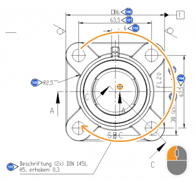 | 3) The characteristic numbers have been re-numbered corresponding to their position relative to the center point: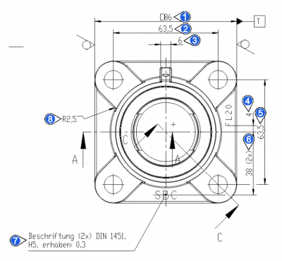 The next free number is displayed in the field for the start number. Note If a number has already been assigned, the next free number is always automatically selected. |
||
| 2c | Number in reading direction | 1) Select the characteristics to be numbered, either by selection in the characteristics list or on the drawing sheet (see also User interface > Operation – Special features when selecting). | 1) The desired characteristics are selected. The drawing view mentioned in step 1 is to be re-numbered consecutively in the example. |
| 2) Click on the Number in reading direction button ( | 2) The characteristics are now numbered in the reading direction (from left to right and top to bottom):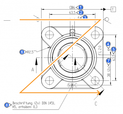 The next free number is displayed in the field for the start number. Note If a number has already been assigned, the next free number is always automatically selected. |
||
| 2d | Renumber by list position | 1) Select the characteristics to be numbered, either by selection in the characteristics list or on the drawing sheet (see also User interface > Operation – Special features when selecting). | 1) The desired characteristics are selected: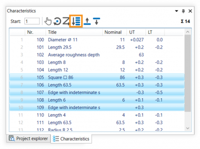 |
| 2) Click on the Renumber by list position button ( | 2) The characteristic numbers have been re-numbered corresponding to their position in the characteristic list: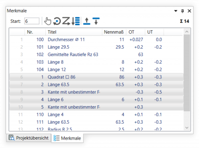 The next free number is displayed in the field for the start number. Note If a number has already been assigned, the next free number is always automatically selected. |
||

(Full functional description: Functions > Export > Export drawing
| Step | Action | Result | |
|---|---|---|---|
| [1] | [Optional] Prepare view | Instead of exporting all contents, you can also export only a section of the contents of a sheet. You define the view as follows. Open the drawing sheet and fit the desired section into the window. For example, use the view tools Dynamic zoom ( 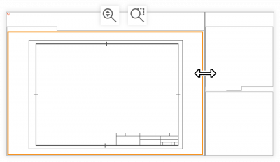 | The desired section is fitted into the drawing window.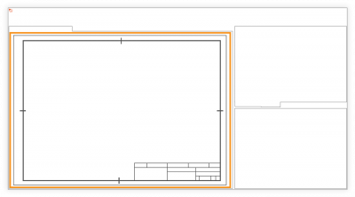 |
| 2 | Select the drawing sheets | In the Project overview window, right-click on the test plan version whose drawing sheets you want to export or on the drawing sheet if you only want to export this one. Select the Export as PDF ( Note Export of several sheets to one file is possible from program version 3.3.4. | The Export document to PDF dialog window opens. |
| 3 | Check export settings | Here you can check the export parameters and settings and make changes if necessary: Content Export the entire drawing sheet or limit the exported section to the current view see Step 1, Prepare view Page format Set the size of the sheet (default size or custom size) Color filter Specify which elements are to be displayed in color, gray or black and white Properties Save metadata as document properties Convert text to geometry Export characters as vectorized geometric elements Open PDF after export Open the exported file with the program set as default after the export is complete. | The export settings are correct. |
| 4 | Export drawing | Click Export at the bottom of the dialog box. In the file manager that opens, specify the location and file name. | The drawing sheet has been exported and saved in the specified location. |
| PNG, TIF, JPG, BMP, GIF | |||
| 1 | Check export settings | Make sure that the export format for drawings is set correctly. Open the Settings menu via Edit (menu bar) > Settings > Export. In the group Drawing graphics you can check the settings and change them if necessary. See also Settings > Preferences > “Drawing graphic format” group group | The settings are as desired. |
| 2 | Select drawing sheets | In the Project overview window, right-click on the test plan version whose drawing sheets you want to export as a graphic. In the context menu, select Export to multiple files > Drawing Graphic. | The Browse Folder dialog box opens. |
| 3 | Export drawing sheets | Select the location in the directory tree and click OK. | The drawing sheets have been exported. |
| SVG | |||
| 1 | Select drawing sheet | In the Project Overview window, right-click on the drawing sheet you want to export. In the context menu, select the function Export as SVG. | The dialog window Export drawing sheet version to SVG opens. |
| 2 | Check export settings | The export parameters and settings can be checked and changes made if necessary in the Export document as SVG dialog window: Layout export settings Export the drawing sheet with or without stamps. Options Export drawing elements in monochrome or in the original colors (Monochrome mode); open the exported file with the program set as default after the export is complete. | |
| 3 | Export drawing sheet | In the directory tree, select the location and click Export. | The drawing sheets have been exported. |

(Full functional description: Functions > Export > Export test plan)
| Step | Action | Result | |
|---|---|---|---|
| 1 | Select test plan | In the Project overview, right-click on the test plan version you with to export and then place the cursor over the list entry Export as in the context menu that opens. | 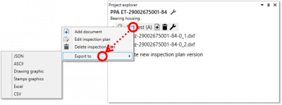 |
| 2 | Export test plan … | The test plan can now be … 2a) …exported in JSON format. 2b) … exported in ASCII transfer format. 2c) … exported in CSV format. 2d) … exported to an Excel file. |
|
| 2a | … in JSON format | In the sub-menu of the context menu, click on Json. | In the file manager window that opens, you can now save the file as usual in a location of your choice |
| 2b | … in ASCII transfer format | 1) In the sub-menu of the context menu, click on ASCII transfer format. | 1) The Export in ASCII transfer format dialogue window will open: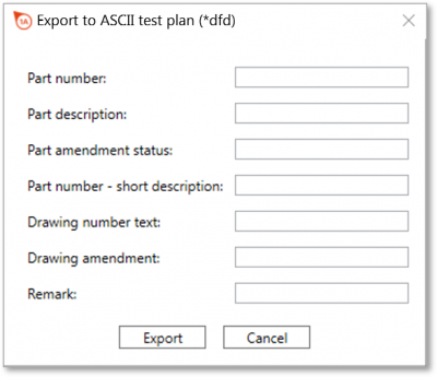 |
| 2) Here, you can enter data for the file header and then click on Export. | 2) In the file manager window that opens, you can now save the file as usual in a location of your choice | ||
| 2c | … in CSV format | In the sub-menu of the context menu, click on CSV. | In the file manager window that opens, you can now save the file as usual in a location of your choice |
| 2d | … to an Excel file | 1) In the sub-menu of the context menu, click on Excel. Note Microsoft Excel must be installed on the computer to execute the export. | 1) The Export to an Excel file dialogue window will open: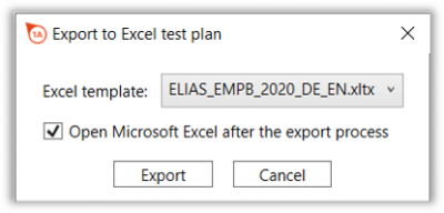 |
| 2) Here, you can now select the Excel template file and check the Open Excel box if you want Microsoft Excel to open once the export is complete. Then, click Export. | 2) In the file manager window that opens, you can now save the file as usual in a location of your choice | ||